-
Posts
1,855 -
Joined
-
Last visited
-
Days Won
173
Everything posted by developer_mh
-
Hallo, die schlechte Nachricht zuerst: Die Trinkwarmwasserbereitung mit einem Heizstab, der mit dem PV Überschuss betrieben wird, ist derzeit leider nicht möglich. Aber die gute Nachricht ist, dass es in der nächsten großen Version (PV*SOL premium 2021, das für den späten Herbst geplant ist) kommen wird. Momentan bleibt dem Anwender nur, sich den Überschuss (also die Netzeinspeisung in derzeitigen Anlagenarten) zu exportieren und selbst abzuschätzen, welcher Teil davon von einem Heizstab umgesetzt werden kann. Ist aber natürlich etwas Arbeit und nicht sehr genau. Beste Grüße, Martin
-
Dear Charles, I don't see a header in your xlsx, so perhaps this is what you were missing? You'll need something like this before your actual data: Location Name 52.3032,-13.2556,50,-1,-30 Ta Gh FF RH ... The format of the header information is described here: https://help.valentin-software.com/pvsol/2020/pages/system-type-climate-and-grid/meteosyn/#options Hoepe that helps, kind regards, Martin
-
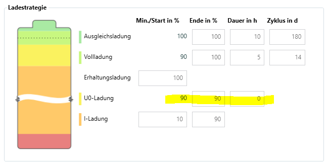
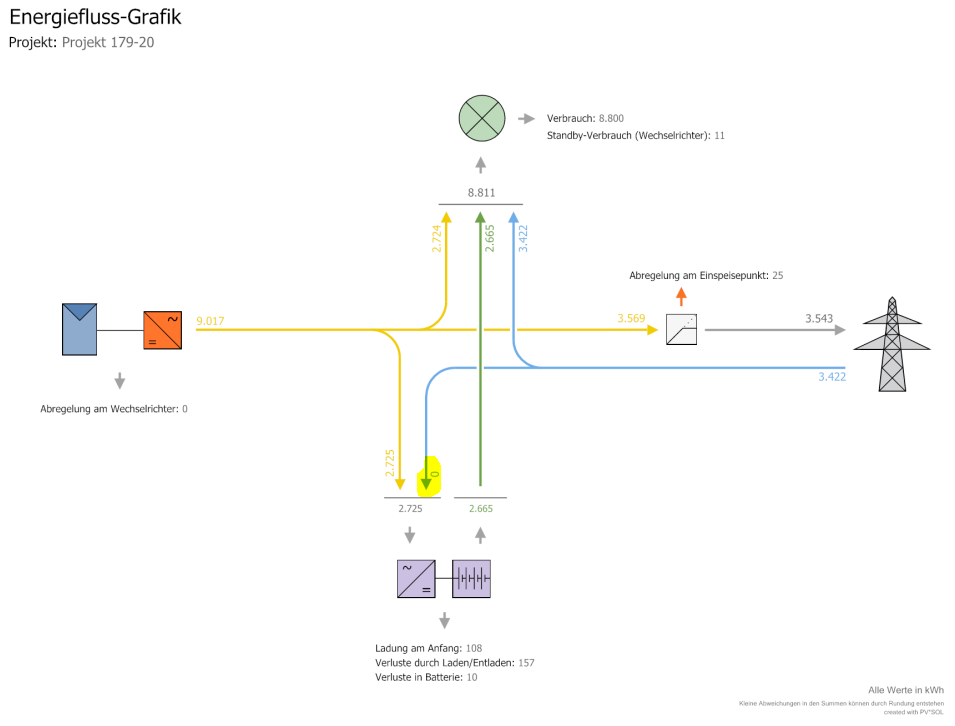
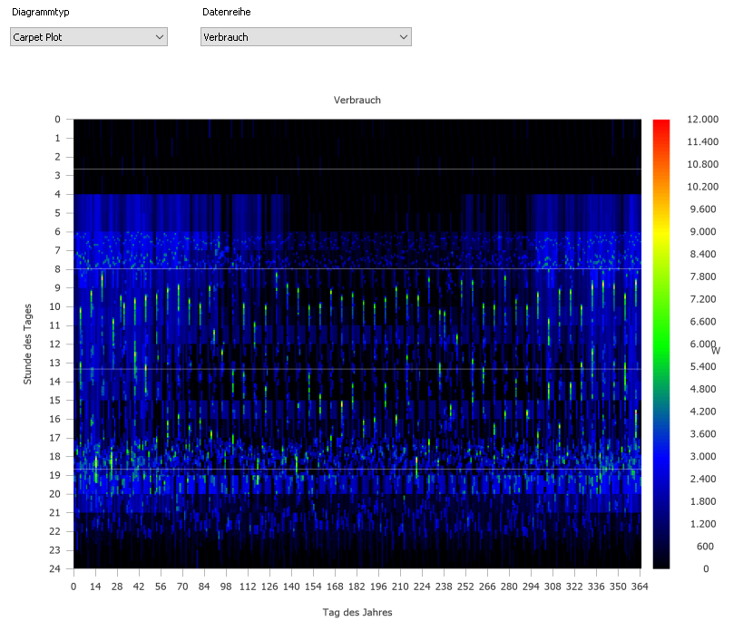
Hallo Ralf, danke für das Projekt. Es ist so, wie ich vermutet hatte, die Ladestrategie führt bei dieser Systemgröße (Anschlussleistung 2 x 60 kW, Kapazität 122 kWh) dazu, dass beträchtliche Energie-Mengen aus dem Netz geladen werden müssen. Die PV hat ja nur etwa 10 kWp, sie kann also selbst im besten Fall nur unwesentlich zur Boost-Ladung (U0-Ladung) beitragen. Ich habe testweise mal eine Kopie des Batteriespeichers angelegt und die Ladestrategien wie folgt angepasst: Damit wird die U0-Ladung deaktiviert und die Ladung aus dem Netz findet nicht statt. In der Realität kann so etwas aber natürlich passieren. Bei solchen Anlagen-Dimensionen sollte man sich dessen bewusst sein. Ein weiterer Punkt, auf den ich im Zusammenhang mit überdimensionierten Speichern aufmerksam machen möchte, ist der Last-Bereich, in dem der Speicher gefahren wird. Der Verbrauch hat zwar eine Spitzenlast von 11kW, aber die meiste Zeit über Lastwerte von unter 5 kW: Wenn diese Last also aus dem Speicher gedeckt werden soll, liegt dessen Auslastung bei etwa 5kW/(2*60 kW) = 0,042, also 4,2%. Sehr oft auch darunter, wie die blauen bis schwarzen Bereiche in obiger Grafik zeigen. In diesem Bereich arbeiten wohl auch die besten Leistungselektroniken nicht mehr effizient, und es wird wertvolle Energie durch geringe Umwandlungsverluste verschenkt. Beste Grüße, Martin
-

Kombination Freiflächenanlage mit Gebäudeanlage: Vergütung, EEG-Umlage auf EV
developer_mh replied to EAN's topic in PV*SOL
Hallo EAN, die Kombination von getrennten Erzeugungsanlagen und verschiedenen Einspeisetarifen ist derzeit nicht möglich. In deinem Fall würde es wahrscheinlich gehen, die beiden Anlagen getrennt voneinander durchzurechnen. Zuerst die Freiflächenanlage ohne Einspeisetarif zur Eigenstromnutzung, und im Anschluss die Gebäudeanlage mit Einspeisung nach EEG. Wenn man es ganz genau haben möchte, könnte man sich den Netzbezug nach der ersten Simulation exportieren und diesen als Rest-Lastprofil für die zweite Simulation verwenden. Beste Grüße, Martin -
Hallo Gerald, leider gibt es derzeit keine derartigen Lastgänge in PV*SOL. Mir ist auch nicht bekannt, wo es welche geben könnte, aber vielleicht weiß jemand aus dem Forum mehr? Beste Grüße, Martin
-
Hallo Kristian, entschuldige die späte Antwort. Könntest du uns die dat-Datei zukommen lassen? Am besten per private message hier im Forum. Danke! Viele Grüße, Martin
-
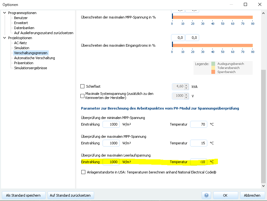
Hallo bene-solar, tatsächlich, PV*SOL kann derzeit nicht mit unterschiedlichen Temperaturkoeffizienten für verschiedene Spannungsbereiche umgehen: Ein Trick wäre, (nur) für diese Module die Prüftemperatur der Leerlaufspannung auf von -10°C auf 25°C zu setzen: Beste Grüße, Martin
-
Hallo Ralf, spannende Frage! Im Detail lässt sich das am besten mit der Projektdatei klären. Könntest du sie mir zukommen lassen, z.B. hier per private message im Forum? Ein erster Tipp geht in die Richtung der Ladestrategie des Batteriesystems. Es gibt dort Pflegeladungs-Modi (Boost-, Voll- und Ausgleichsladungen) die bei so einer Batteriegröße ganz schön ins Gewicht fallen können. Beste Grüße, Martin
-
Hallo Alexander, die von dir beschriebene Heransgehensweise ist genau die richtige. Da gibt es momentan keinen anderen Weg. Beste Grüße, Martin
-
Hi Benjamin, very sorry for the super late reply. Somehow this post (and appearently another one for that topic) was forgotten. I spoke to my colleagues, and it is not possible to define a reference edge for imported models, I am afraid. But we will put that on our feature request list. Sorry again fot letting you wait so long, kind regards, Martin
-
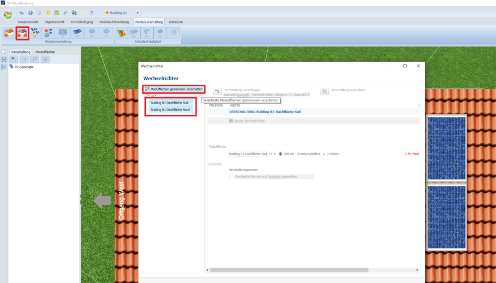
Hallo Sebastian, die Funktion, die du gefunden hast, ist praktisch, um Modulflächen zu vereinigen. Um Modulflächen (auch ganz unterschiedliche) miteinander zu verschalten, musst du das aber nicht tun. Es reicht, bei der Verschaltung beide Modulflächen zu selektieren, dann oben auf den Button "Gemeinsam verschalten" und dann die Option Polystring wählen. Dann hat man alle Freiheiten. Beste Grüße, Martin
-
Dear Waqar Ahmad, the energy balance lists the energy gains and losses of the PV system, from the irradiation to the AC grid energy of the system. You can find more here: https://help.valentin-software.com/pvsol/2020/pages/results/energy-balance/ Kind regards, Martin
-
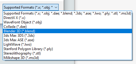
Hi Paul, yes, this is possible. At the moment PV*SOL premium can import the followig 3D formats: In practice, it is a bit difficult to say which format works best. It all depends on the software that is exporting the files, and also how the 3D model itself is structured. Often obj and 3ds files work well. Hope that helps. If you have further questions, please don't hesitate to ask. Kind regards, Martin
-
Hallo Sebastian, ja, auch das geht. Einfach die Modulflächen gemeinsam verschalten und dann die Option Polystring wählen. Damit kann man alle erdenklichen Verschaltungen realisieren. Viel Erfolg und beste Grüße, Martin
-
Dear Waqar Ahmad, the horizon line is representing the border between the visible sky and the surrounding (hills, mountains, far buildings etc), from the point of view of the PV array. Here you can find more information: https://help.valentin-software.com/pvsol/2020/calculation/irradiation/horizontal-shading/ https://help.valentin-software.com/pvsol/2020/pages/pv-modules/shading/ Hope that helps, kind regards, Martin
-
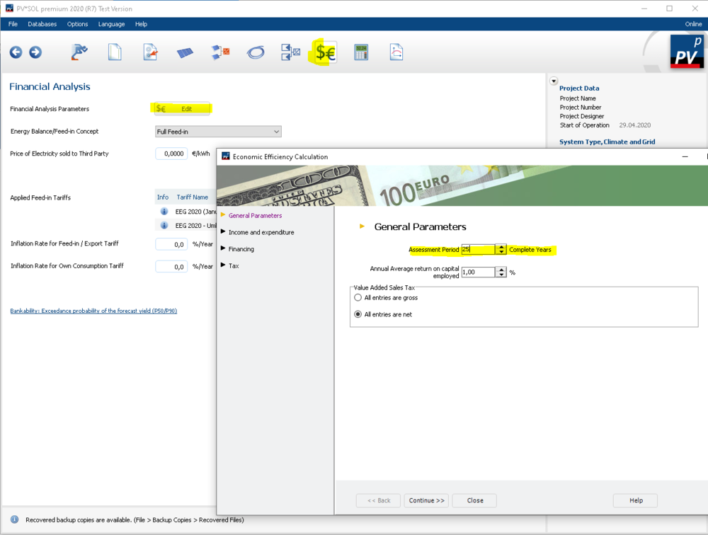
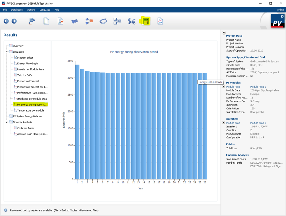
Dear Waqar Ahmad, in order to see the 25 years of annual yield, you'll have to change the time range of the assessment period to 25 years. This can be done in the economy settings: Then simulate, and find the diagram of the annual yield here: Hope that helps, kind regards, Martin ps: Please try to find a suitable description for your threads, like in this case "Diagram for annual PV yield over 25 years" or so. Then it will be easier to find also for other forum users.
-
Hi Anton, yes, the power figures must be taken from the datasheet of the MultiPlus-II and then entered into PV*SOL either for the PV inverter or the battery inverter. You'll have these two devices in PV*SOL that represent the one MultiPlus-II device. Kind regards, Martin
-
Hallo Michael, bei der Berechnung der Abschattung in 3D, also wenn man aus der 3D-Visualisierung zurück zu PV*SOL kehrt, ist eine gute GPU-Leistung vorteilhaft. Für die eigentliche Ertragssimulation, also vor der Seite "Ergebnisse" ist eine gute single core (auch "single thread") Performance vorteilhaft. Diese ist auch generell für die Nutzung von PV*SOL hilfreich. Beste Grüße, Martin
-
Dear Jan, one way would be to remove the electrical appliances from the project, that is, set the project type to "Grid connected PV system". But this is perhaps not what you want. The other option would be to set the from-grid price to 0 €/kWh, then the electricity savings don't appear in the cash flow. Hope that helps, kind regards, Martin
-
Dear Sarah, these kind of systems are currently not supported in PV*SOL, I am afraid. We have this topic already on our list, but I can't tell a date for the release right now. Kind regards, Martin
-
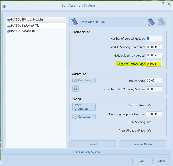
Dear Waqar, you can define the height of the mounting structure here: This dialog pops up when you create a new module mounting system. Hope that helps, kind regards, Martin
-
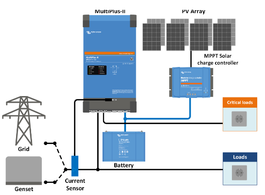
Hi Anton, the Victron MulitPlus II approach is somewhat different to our ongrid and offgrid system types. I'd interpret it as offgrid for the PV (as it does not feed into the grid), but ongrid for the loads (as loads are covered by grid energy). In case of grid outage, it would clearly be a DC coupled battery offgrid system: I think the most suitable way to model this in PV*SOL would be an offgrid system with diesel backup generator, and you interpret the generator energy as from grid energy. In offgrid systems in PV*SOL you can also define load shedding, which might be useful for this kind of application. Then, you define a PV inverter with the MPP tracker properties of the MPPT solar charge controller. The DC/AC efficiency would be your DC/DC efficiency of the solar charger. And then you need an offgrid battery inverter with the corresponding properties of the MultiPlus-II. This should give you results that are as close as possible with PV*SOL at the moment. Let me know if this helps. If you need any further assistance, please don't hesitate to ask. Kind regards, Martin
-
Hi Anton, do you have a schematic drawing of your system? Perhaps we can find a system type that comes close to your application. But a pure DC coupled offgrid system is not possible right now in PV*SOL, I am afraid. Kind regards, Martin
-
Hi Frido, yes, I do exactly understand what your points are, thank you for letting us know. We have these features requests and tweaks on our list, but right now I can't say when they could be released. For your first and initial problem, there might be a viable work-around (which I used for my screenshot as well). If you use module mounting systems instead of module coverage it should work as you expected. Module coverage relies on a fixed grid, which is why the outcome is like in your image, buiding B1. When covering the roof, the strict grid is followd, and if there is an obstacle or barred area, the module will not be placed. For a lot of applications, this might be the wanted behaviour. When using module mountings, you don't have this fixed grid, but each row is placed independently, so it results in a layout like in my screenshot. Give it a try and let me know if this does the trick for you. Kind regards, Martin


