


developer_mh
-
Posts
1,855 -
Joined
-
Last visited
-
Days Won
173
Everything posted by developer_mh
-

unexpected warning ...from-grid tariff is not valid...
developer_mh replied to R040l's topic in PV*SOL
Dear Rob, sorry for the late reply. What I wanted to say is that the feed-in tariff is not the problem here, but the from-grid tariff. The feed-in tariff is for the Netherlands, that is right and correct. The from-grid tariff however is from Germany and that is why the warning message appears. Kind regards, Martin -
Hallo Alexander, im Schaltplan werden externe Leistungsoptimierer mit einem kleinen Sternchen gekennzeichnet. Hier sind z.B. 5 Module ohne Optimierer mit zwei Module mit Optimierer und wieder einem Modul ohne Optimierer in Reihe geschaltet Beste Grüße, Martin

-
Hallo Matthias, ja, da gibt es eine Funktion in der 3D Rendering Engine, die in Abhängigkeit der Anzahl von sichtbaren Objekten die Art der Darstellung anpasst, um die Performance zu erhöhen. Es handelt sich aber um eine rein optische Anpassung, die Simulation oder andere Teile des Programms sind nicht davon betroffen. Beste Grüße, Martin
-
Dear Waqar Ahmad, the circuit diagram can be accessed at the page "Plans and parts list". You can edit the security devices and cable properties at the page "Cables". Kind regards, Martin
-
unexpected warning ...from-grid tariff is not valid...
developer_mh replied to R040l's topic in PV*SOL
So I will post our private conversation here (in extracts): Rob's reply: My reply: As for the tariff problem: The net metering tariff is for the Netherlands, that is right, but the from-grid tariff (the second one) is for Germany: Hope that helps, kind regards, Martin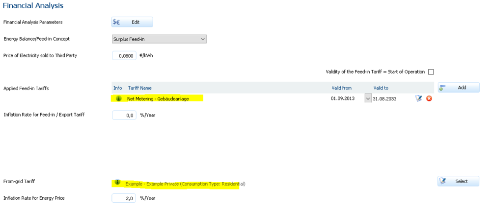
-
Dear Waqar Ahmad, you will have to go into the 3D environment of PV*SOL, and then either imitate a curved building with segments of straight buildings or import a 3D model from Sketchup or similar applications. Refer to these threads as reference: Hope that helps, kind regards, Martin
-
unexpected warning ...from-grid tariff is not valid...
developer_mh replied to R040l's topic in PV*SOL
Hi Rob, I just wrote an answer to your questions in the private message section. If you allow, I'll post it here so that the other users can read it as well. Kind regards, Martin -
unexpected warning ...from-grid tariff is not valid...
developer_mh replied to R040l's topic in PV*SOL
Hi Rob, here as well, a project file would be handy in order to see what is going on there. Thanks a lot, kind regards, Martin -
Hi Rob, could you provide a project file? You can send it via private message here in the forum. This would make an answer easier. Thanks a lot, kind regards, Martin
-
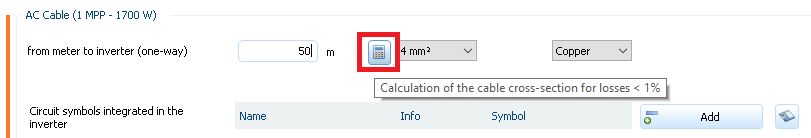
Dear Waqar Ahmad, the cable length is something that you enter in PV*SOL. The cable size can then be calculated so that the cable losses at STC (Standard Test Conditions) are below 1%. Go to the cable page and activate "detailed" view. Then you see these inputs: Hope that helps, kind regards, Martin
-
Hi Vishnu, at the moment you can only add batteries to one inverter. This is due to the underlying simulation algorithms. But we have that feature request on our list and we will try to implement it as soon as possible. Kind regards and best wishes, Martin
-
Hi Josh, the module data entered by the manufacturers is only checked against min/max values, we do not require a third party report. The manufacturers are responsible for the data they enter. But if we encounter irregularities, we usually contact them to clarify the issue. The model we use to calculate the reflexion losses is the one from AHSRAE: https://help.valentin-software.com/pvsol/2020/calculation/pv-modules/reflection-in-module-plane/ Hope that helps, kind regards, Martin
-
Hallo MB, bekannt ist mir das Problem nicht, aber für klingt es so, als sei das Fenster der 3D-Visualisierung auf dem nicht mehr vorhandenen zweiten Monitor geöffnet. Hast du mal versucht, den externen Monitor wieder anzuschließen und dann nochmal die 3D-Umgebung zu starten? Beste Grüße, Martin
-
Hallo, sorry, meine Inbox hier im Forum war voll. Probier es jetzt nochmal. Beste Grüße, Martin
-
Hallo Leman, mir kommt gerade der Verdacht, dass das evtl was mit der Zeitzone zu tun hat. Könntest du mir mal zwei PV*SOL Projekte zukommen lassen, einmal mit Standard-Klimadaten und einmal mit den neuen TRY? Das wäre super, danke. Beste Grüße, Martin
-
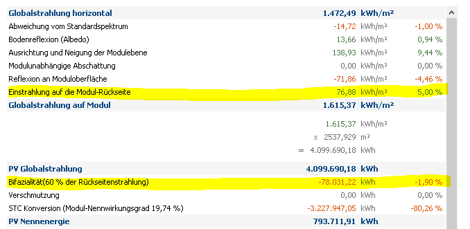
Hallo Julian, im ersten Block der Energiebilanz kommen 76,88 kWh/m² Strahlung auf die Rückseite dazu. Die kämen nicht dazu, wenn man mit monofazialen Modulen rechnet. In Summe macht das bei einer PV-Fläche von 2537,929 m² einen Strahlungsgewinn auf die Rückseite von 195116 kWh. Das ist das, was in der ersten gelb markierten Zeile verzeichnet ist. Da das Modul aber nicht 100% der rückseitigen Strahlung umsetzen kann (Bifazialitätsfaktor von 60% in deinem Fall), werden 40% der rückseitigen Strahlung wieder abgezogen, bevor es mit der eigentlichen photoelektrischen Konversion weitergeht. 78031,22 kWh / 195116 kWh = 40%. Mehr dazu auch hier: https://help.valentin-software.com/pvsol/2020/berechnungsgrundlagen/pv-module/bifaziale-module/ Beste Grüße, Martin
-
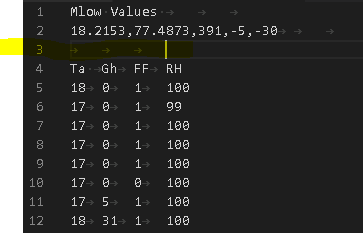
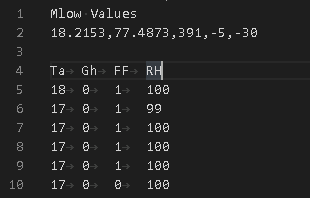
Hi Dongash, I guess it is line 3, as mentioned in our previous conversation, and the whitespace (space) right after the column name "Ta". Copy the values from your Excel sheet to a text file, remove the (invisible) tabs in line 3 and at the end of lines 1 and 2, remoe also the whitespace after Ta in line 4 (only the space, not the tab), then save as *.dat. That should work. This doesn't import. This works. Hope that helps, kind regards, Martin
-
Hallo Julian, sieht doch gut aus.. schau mal in die Energiebilanz bei den Ergebnissen: Beste Grüße, Martin
-
Hi Waqar Ahmad, this behaviour of the software is unknown to us. Which version are you using? Please deinstall your current PV*SOL, and download and install a fresh version here: https://valentin-software.com/en/downloads/ Then everything should be fine again. Kind regards, Martin
-
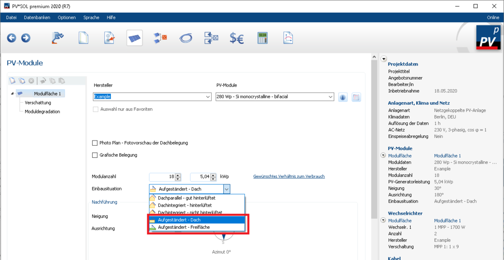
Hallo Julian, bei den bifazialen Modulen kommt es darauf an, wie sie installiert werden. Je nach Einbauart simulieren wir die Strahlung auf die Rückseite mit oder nicht. In der 3D-Umgebung müssen die Module dafür aufgeständert sein, nicht flach auf einem Dach installiert. In 2D, also in der nicht-3D-Planung ist eine aufgeständerte Einbauart zu wählen. Dann erscheint unterhalb auch die Editiermöglichkeit für die bifazialen Module bzw. deren Aufständerung. Viele Grüße, Martin
-
Hallo Leman, vielen Dank für das Senden der Daten (für die anderen Leser: Es handelt sich um die aktuellsten TRY-Daten des DWD). Ja, es ist möglich mit diesen Dateien. Allerdings muss man sie vorher etwas umstruktieren, aber mit Hilfe eines Text-Editors und Excel ist das kein Problem. Die Daten müssen in das Format gebracht werden, das hier beschrieben ist: https://help.valentin-software.com/pvsol/2020/navigationsseiten/anlagenartklimaundnetz/meteosyn/#optionen Es werden also nur die Spalten Ta ("t" in der DWD-Datei), Gh ("B" + "D" in der DWD-Datei), FF ("WG" in der DWD-Datei) und Rh ("RF" in der DWD-Datei benötigt). Ansonsten sollte sich der Aufbau der zu importierenden dat-Datei aus der Beschreibung, die ich oben verlinkt habe, ableiten lassen. Wenn du dazu noch Fragen hast, immer gerne. Viele Grüße, Martin ps: Wir planen, diese TRY-DWD-Datensätze auch in PV*SOL zu integrieren, sodass in Zukunft kein händischer Import mehr vonnöten sein wird.
-
Hallo Lema, das Export-Format vom DWD, das wir kennen und unterstützen, ist das xlm-Format. Eine dat-Datei habe ich vom DWD noch nicht gesehen, könntest du sie mir mal schicken, dann kann ich mir das mal anschauen. Am besten per privater Nachricht hier im Forum. Beste Grüße, Martin
-
Hallo Lars, wir hatten in der Tat gestern zwischen 15:30 und 16:40 Probleme mit den Servern, wie auch letzten Donnerstag. Dies sind die ersten Ausfälle dieser Art. Wir sind noch dabei, die Vorfälle zu analysieren. Das Zurückgreifen auf die Offline-Datenbank scheint bei vielen unserer Kunden nicht funktioniert zu haben, da die Online-Datenbank nicht ganz offline war, sondern suggeriert hat, dass eine Verbindung noch möglich sei. Der Umgang von PV*SOL mit einer labilen, aber nicht vollständig fehlenden Verbindung zur Online-Datenbank wird in einem nächsten Release verbessert. Und natürlich arbeiten wir weiter an der Absicherung der Online-Datenbanken, damit so etwas hoffentlich nicht noch einmal passiert. Vielen Dank für die Rückmeldung jedenfalls, beste Grüße, Martin
-
Dear Waqar Ahmad, can you describe what you intend to do with the license file? Usually all processes related to the software license can be handled from within the software. And please try to gice your topics a meaningful title in the future, not your own name. Kind regards, Martin
-
Hi Dongash, I guess it was due to the tab character in line 3 that the import failed. Please find attached a working dat file. Kind regards, Martin PGentle.dat


