


developer_mh
-
Posts
1,860 -
Joined
-
Last visited
-
Days Won
173
Everything posted by developer_mh
-

The scale of the building does not correspond to the scale of the loaded map
developer_mh replied to Andrii's topic in PV*SOL
Hi Andrii, this is interesting. Could you provide us a project file with the described map section and 3D model? You can send it here in the forum as private message. Thanks a lot, kind regards, Martin -
Hi Bill, this is just an inaccuracy in the translation of the 3D environment. "Flush Mount" is the type you are looking for. Kind regards, Martin
-
Dear Wouter, dear Jimmy, we really appreciate how you discuss with each other and help you out! Could you try to reduce the model so that only the lower block remains and then convert it into an obj file? Which software are you using for modelling and converting dwg to obj? Kind regards, Martin
-
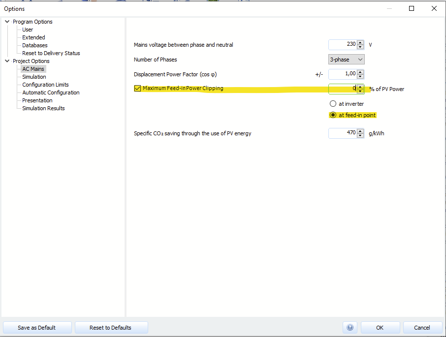
Dear Gorka, you can avoid a grid feed-in if you set the maximum feed-in power clipping to 0 % at the feed-in point in the dialog of the AC grid: Concerning your last question: Thanks for pointing that out, we will put that on our list. Kind regards, Martin
-
Auto in PV-Sol - Verbesserungsbedarf PV Überschussladen
developer_mh replied to RLoos's topic in PV*SOL
Hallo Finn, dazu gibt es leider noch kein Update. Auch im nächsten Release wird es nicht enthalten sein, tut mir leid. Wir mussten andere Dinge priorisieren. Viele Grüße, Martin -
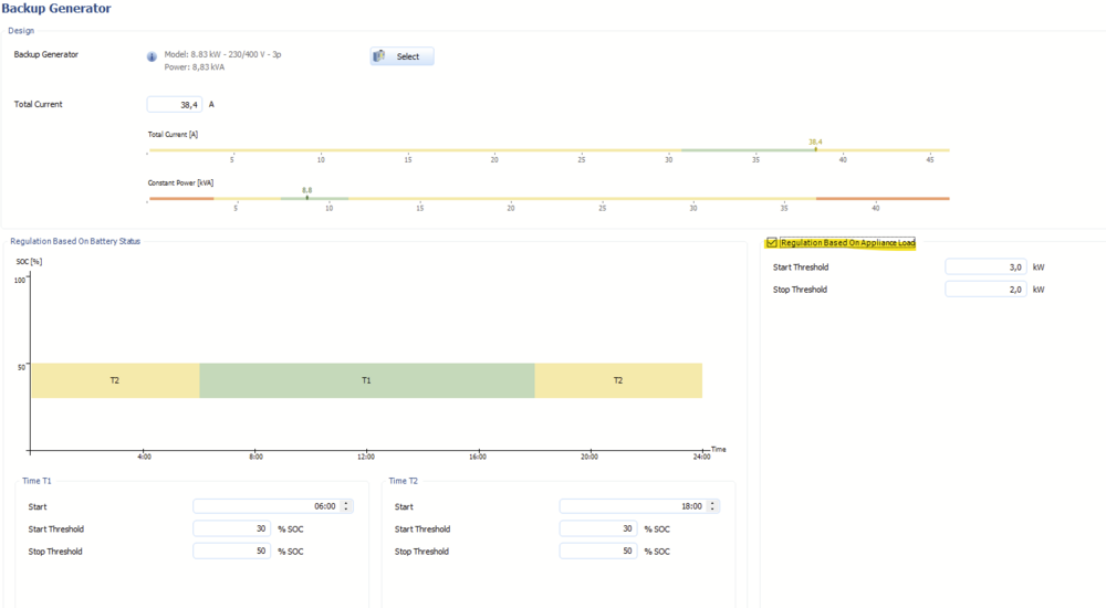
Hallo Marko, entschuldige die späte Antwort. In diesem Fall liegt es an der Regelung des Backup-Diesel-Generators, der auf Laststeuerung gesetzt ist: Diese Einstellung führt dazu, dass der Generator fast immer läuft, da die Last in diesem Projekt fast immer über 3 kW liegt. Der Generator sorgt dann dafür, dass die Last immer von ihm gedeckt wird und die Batterien immer voll sind. Sie sind damit so gut wie wirkungslos. Ohne diese Laststeuerung funktioniert die Auslegung wie gewünscht. Viele Grüße, Martin
-
Hallo Gero, entschuldige die späte Antwort. Geht es um die Planung mit PhotoPlan in PV*SOL? Oder könntest du vielleicht mit einem Beispielbild näher erläutern, wo es hakt? Besten Dank und viele Grüße, Martin
-
Hi aponsa, the decision which economic concept you must apply does not depend on the feed-in clipping. It does depend on your local tariff. In Germany for example with have surplus feed-in tariffs. In other countries like Brazil or Poland, net metering tariffs prevail. Kind regards, Martin
-
Problem with caltulation of shading of lower buildings
developer_mh replied to David Heneš's topic in PV*SOL
Dear David, regarding the shading calculation, please verify that the following option is checked: If you enter the 3D environment and return to the main application, the calculation of the shadings should occur. Then you should also see the yield reduction due to shading in the results. A specific annual yield of 913 kWh/kWp is nothing unusual for a PV system without shading (which is the case in your example where the shadows where not calculated). We don't know where you read that, but to clear up misunderstandings: The new 3D environment will not be released November of this year, I am afraid. It was never planned to be released this year, so I am sorry if we were communicating that unprecisely earlier. Kind regards, Martin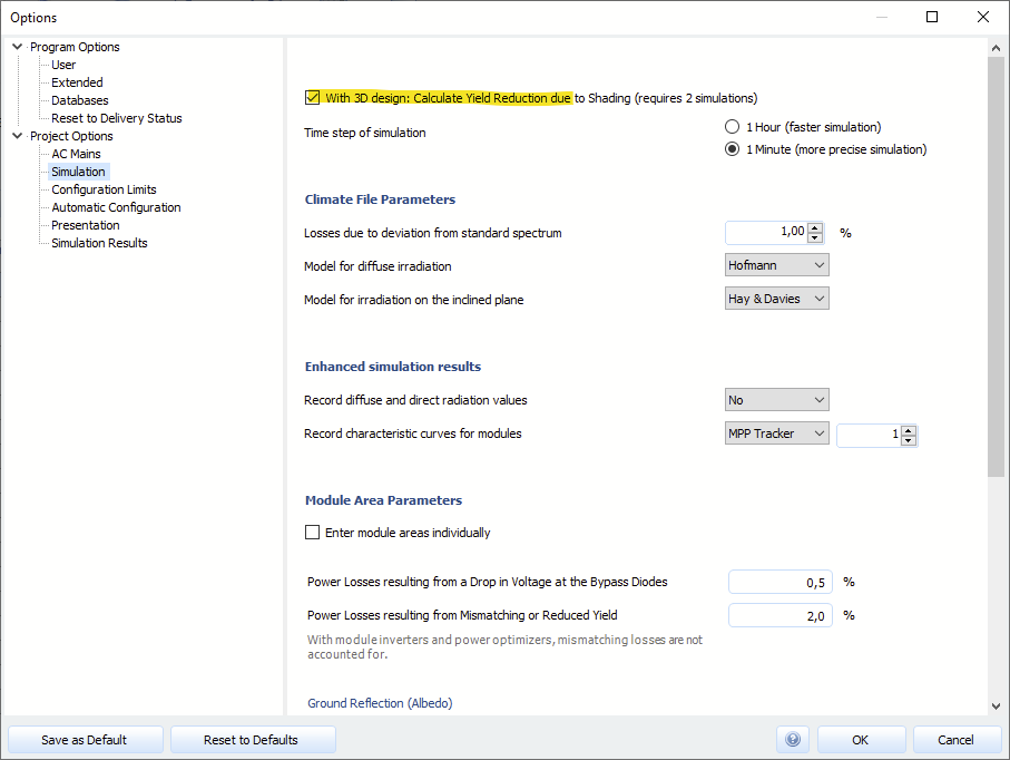
-
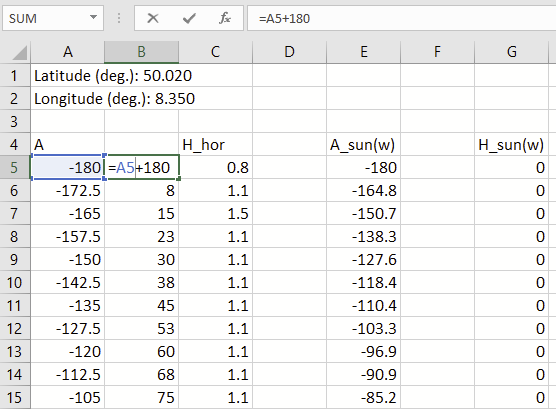
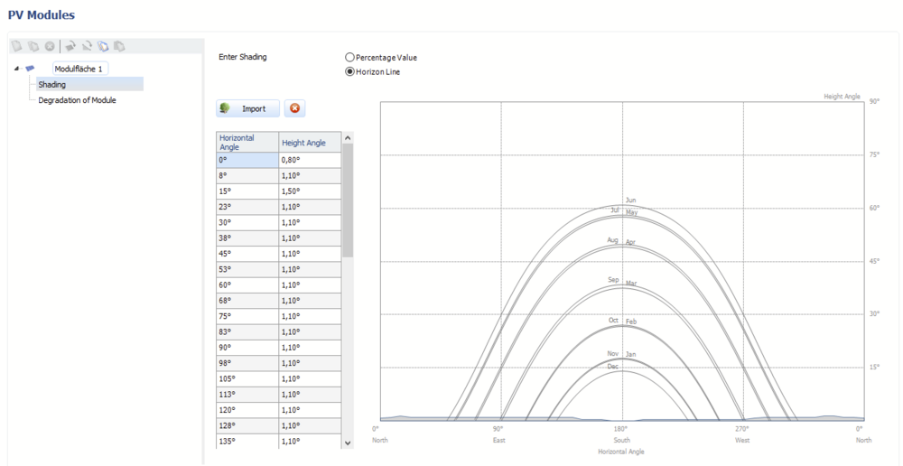
Hi Sondre207, first of all: The import of PVGIS horizons will be a built-in feature in the upcoming major release, PV*SOL premium 2022 R1, due this autumn/winter. In the meantime you can simply open the exported csv file in Excel or any other spreadsheet software, and add 180 to the azimut values in another column, like so: Then you can just copy the azimuth and the elevation column (B and C in this example here), and paste it into the horizon table in PV*SOL: Hope that helps, kind regards, Martin
-
Hallo Pommesfän, das ist im Prinzip richtig, die Leistungsoptimierer bestimmen letztendlich die Spannung, die dann am Wechselrichter anliegt. Die Ausgabe der durch die Module entstenden Leerlauspannung ist hier auch nur ein warnender Hinweis, dass es sich lohnt, genauer hinzusehen. Im Fall von Huawei sollten alle Leistungsoptimierer-Verschaltungen in deren Tool verifiziert werden: https://eu.smartdesign.huawei.com:31943/login/login.action Viele Grüße, Martin
-
Fehlermeldung Modulanzahl bei gemeinsamer Verschaltung
developer_mh replied to K. Kurth's topic in PV*SOL
Hallo K. Kurth, die gewünschte Verschaltung mit 2x14 Modulen an einem MPP-Tracker bedingt, dass die 10 Module des Balkondachs mit 4 Modulen des Hauptdachs in Reihe geschaltet werden müssen. Wenn innerhalb eines Strangs Module unterschiedlicher Modulflächen verschaltet werden, ist das eine Polystring-Verschaltung. Die Lösung wäre also: Polystring-Option aktivieren Betriebsart auf MPP1, MPP2 Option "Stränge in Reihe schalten" Dann folgende Verschaltung herstellen: Ich hoffe, das hilft weiter. Viele Grüße, Martin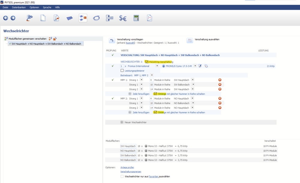
-
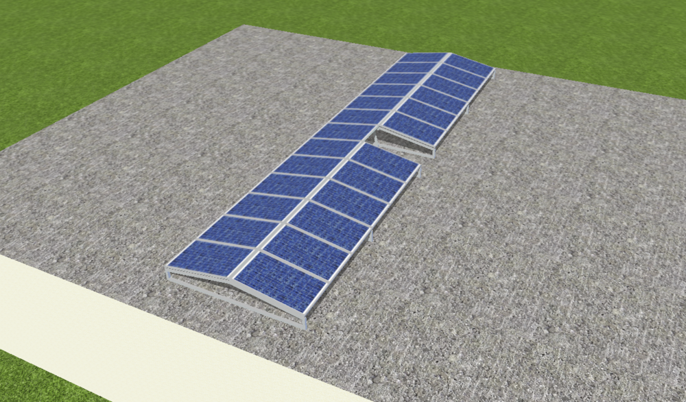
Guten Morgen Tamara, ohne weiteres ist es leider nicht möglich, ein einzelnes Modul aus einer Ost-West-Aufständerung herauszulöschen. Was man aber machen kann, ist, ein Modulpaar aus der Formation zu löschen (dazu trennt man zuerst die Modulreihe unter- und oberhalb des zu löschenden Moduls mit Hilfe der Schere auf). Dann erstellt man ein zweites Montagesystem, diesmal aber kein Ost-West-System, sondern ein einfaches, das den gleichen Neigungswinkel hat wie das vorherige, und als Ausrichtung dann 90° für Westen. Von diesem System zieht man sich ein Modul in die Szene und platziert es zwischen die aufgetrennten Modulreihen: Aufgrund der Sicherheitsabstände musste ich in meinem Beispiel eben auch die obere Hälfte der Modulreihe ausgliedern, um sie einen Tick nach oben zu schieben, da ich sonst das einzelne Modul nicht zwischen die Reihen bekommen hätte. Ich hoffe, das hilft weiter. Viele Grüße, Martin
-
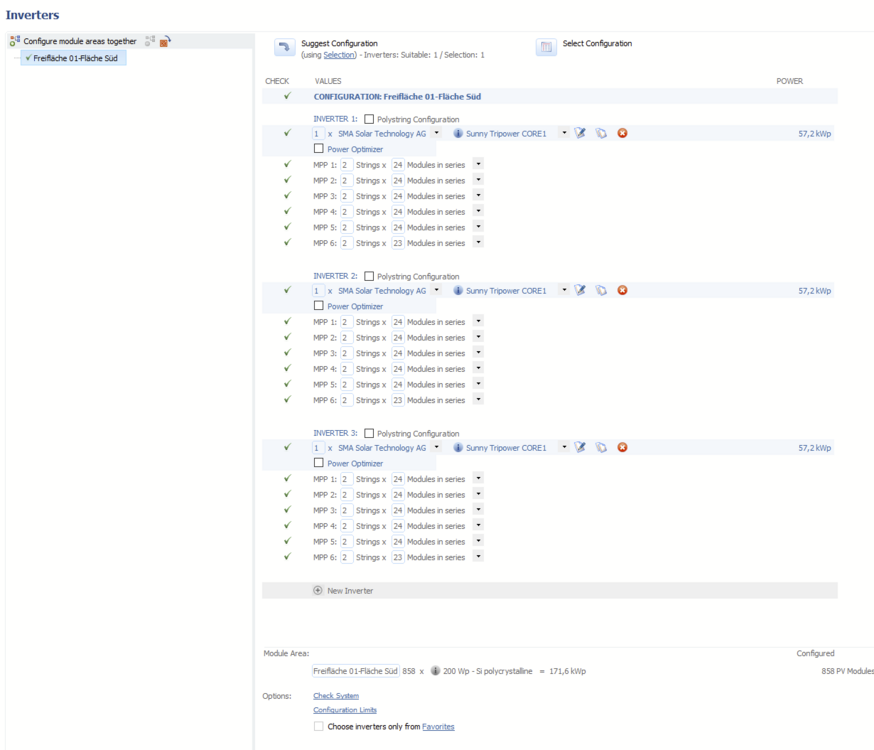
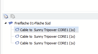
Hi Aljaz, thank you for your question. It is indeed not possible to define separate cables for inverter groups that come from 3D. Even if you split the group in 3D into 16 separate inverters, PV*SOL will combine them into one group again when adopting the data from 3D. I guess this is what you already tried out. In the 2D mode however, you can enter separate equal inverter configurations. They will not be combined by the software. Then you could enter the cabling distances indivually: then in the cable section: So, in 3D mode automatic grouping occurs (for performance reasons). There you would enter the average cable length over your 16 inverters. If you want to plan the cable section for every inverter separately in order to see what it brings, switch to the 2D mode and separate your inverters. I'd recommend saving the 2D apporach into a second project file so that you don't override your 3D planning. Transformer losses can't be entered right now. You'd have to add the transformer losses to the total loss. Hope that helps, kind regards, Martin
-
Hi Jordn, yes, I guess you are right, the naming (more precisely: the english translation) there is incorrect. While ROA (or ROI) is approximately equal to the IRR over one year, they mean something different over the course of several years. Thanks for pointing that out, we will fix it in one of the upcoming releases. Kind regards, Martin
-
Hallo J. Berends, dieses Thema steht schon seit längerem bei uns auf der Liste, ist aber offengestanden noch nicht eingeplant. Es rückt aber immer stärker in den Fokus. Vielen Dank jedenfalls für die Anfrage. Viele Grüße, Martin
-
Hi David, thank you for your questions and welcome to the forum! 1) The extreme shading values that you encouter there are due to an error in our 3D environment that - unfortunately - exists quite some time already. The reason is the attica around the roof, which causes our shading algorithm to think - in some circumstances - that the roof level is actually on the same height as the top level of the attica. So for the algorithm, parts of the modules are below the roof surface, and hence the extreme shading values. They are obviously incorrect, but the algorithm is so complex that we were not able to fix this issue without breaking something else. A workaround is to break up the attica at some point in the circumference of the roof. A small gap in the attica will prevent this from happening. 2) Find more about the limitation in this post here, point 3: So, you can try yourself what your computer is able to manage. Also, we plan to increase these limits in the future, but the exact date is yet unknown. But for us, performance of our software is crucial. Already in the next major release we will be publishing a major amelioration for the RAM usage, so this will already boost the planning of large systems significantly. 3) In order to be able to answer that we would need a project file with the imported simplified landscape, I guess. You can send it to me here in the forum as private message, or better directly to our technical support team at hotline@valentin-software.com Hope that helps, kind regards, Martin
-
Hallo Lukas, das von dir beschriebene Problem ist mutmaßlich mit dem neuen Release, PV*SOL premium 2021 R8 behoben. Könntest du mal testen, ob das Speichern in der neuen Version funktioniert? Viele Grüße, Martin
-
Hi Shubham, in addition to the tutorials that Jimmy pointed out to, a good place to start, especially for stand-alone PV systems, are the example projects that come with PV*SOL, along with the help pages: https://help.valentin-software.com/pvsol/en/pages/system-type-climate-and-grid/ https://help.valentin-software.com/pvsol/en/calculation/offgrid-systems/ Stand alone systems are a bit more difficult to design than ongrid systems, as you might have noticed. There are only few generalizable design rules, and most of them are integrated into the program in the form of hints and warning messages in the bottom part of the program. If you start to design your stand alone project and you run into concrete problems, please don't hesitate to ask your questions here. Kind regards, Martin
-
Ein Gebäude mit unterschiedlichen Breiten erstellen
developer_mh replied to Markus Ziessmer's topic in PV*SOL
Hallo markus, ich denke, für diese Hausform wäre das Extrudieren des Gebäudes aus Polygonen der adäquateste Ansatz. Hier habe ich das Gebäude aus einem Polygon mit 6 Eckpunkten gezeichnet, eventuell ist es aber auch besser, zwei Gebäude mit je 4 Eckpunkten zu zeichnen und diese dann aneinander zu schieben Viele Grüße, Martin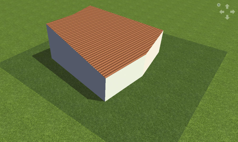
-
Moduloptimierer Tigo Untertypen Kompatibilität zu Wechselrichtern
developer_mh replied to Josua Föttinger's topic in PV*SOL
Hallo Josua, vielen Dank für den Link. Wir werden uns das mal näher ansehen. Im Detail bedeutet das natürlich einen relativ hohen Grad an manueller Pflege dieser Kompatibilitätslisten. Wir nehmen das aber in jedem Fall auf die Liste auf, guter Punkt. Viele Grüße, Martin -
Verkabelung von seriellen Strings im Generatoranschlußkasten
developer_mh replied to Wolfgam's topic in PV*SOL
Hallo Wolfgam, wenn Module auf einer Dachfläche in Reihe geschaltet werden, müssen auch die Kabel auf dem Dach entsprechend gezeichnet werden. Es ist leider nicht möglich, zwei unabhängige Strings zu zeichnen und diese später an anderer Stelle in Reihe zu schalten. Viele Grüße, Martin -
Hi Ginés, I translated your request with deepl.com: You can design a PV system very quickly, without using the 3D environment. Just switch to the non 3D-mode and enter the amount of modules manually. Then choose go to the inverter page and generate an automatic configuration. It takes less than one minute and you are ready to add electrical consumers, battery systems and so on, in order to analyse the desired consumption-production-surplus. Hope that helps, kind regards, Martin
-
Hi Juliana, the reason for the error is that the grid voltage is set to 254.03 V. Our 3D environment can't handle that. Change it to 254 V (or any other value) and it should work. And of course you are free to contact us on any channel that you prefer (mail, forum, phone), but please consider that it might cause double effort for us if you contact us on two channels simultaneously. Kind regards, Martin
-
Dear all, this is a bug that was introduced with the latest version, PV*SOL premium 2021 R7. It will be fixed in the upcoming bugfix release, R8. It affects mounted PV systems with various orientations, like east-west systems, on flat roofs. We are very sorry for the inconvenience caused and try to publish the bugfix release as soon as possible. Kind regards, Martin


