Ricardo
-
Posts
27 -
Joined
-
Last visited
-
Days Won
2
Ricardo's Achievements
")
Newbie (1/14)
3
Reputation
-
Thanks, I look forward to the update when the bug is fixed and hopefully James' idea or something similar is implemented. Kind regards, Ricardo
-
OK, thanks.
-
Hi, When I have an AutoCAD drawing of a building or area as seen from above (top view), I usually import it via the "Coverable object - Map section" under the 3D Design tab. The problem then is to create buildings which have the exact length, width and orientation as those shown in the drawing. What I normally do is to "Sketch a 3D Polygon" which coincides with the drawing as much as possible and then stretch the sides until they are as close to the real dimensions as possible. However, if for example the building's length is 25 m, often I will end up with either 24,976 or 25,012 m but never exactly 25. I know this sounds picky, but sometimes the customer will ask for drawings detailing the module layout and it doesn't look good when the drawings show incorrect dimensions. Is there any way to input the exact dimensions manually? When I try to Edit a building after extruding it, funny results ensue: Thanks and regards, Ricardo
-
Hi, I was wondering, is there an option to undo changes in PV SOL, other than not saving and simply opening the last saved version of your file? Something in the line of Ctrl+Z in MS Office. Thanks!
-
Hi Martin, It does, thanks a lot! Kind regards, Ricardo
-
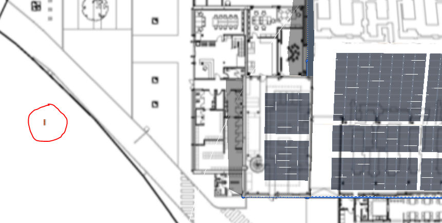
Hi, I recently simulated a big project which could be broken down into three separate smaller projects. I noticed that if I simulated the small projects, the sum of the kWh/year generated in each of them does not add up to the kWh/year generated by the big project. The difference is small (around 0,8%), but still puzzling. In order to find out where the difference might come from, I then simulated a project twice, the second time adding a very minor change which should have no influence in results (a small wall far away from any modules). Again the results changed, by a very small amount, but I would have expected them to be identical. Please see below the wall I placed (1 m long, 0,5 m high), with the closest modules placed on an 8 meter high roof. As mentioned, the difference is minimal, but just out of curiosity, can someone please explain why there is a difference in the first place? Thanks for your support!
-
It does, thanks a lot!
-
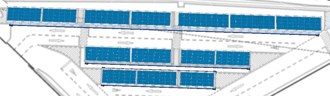
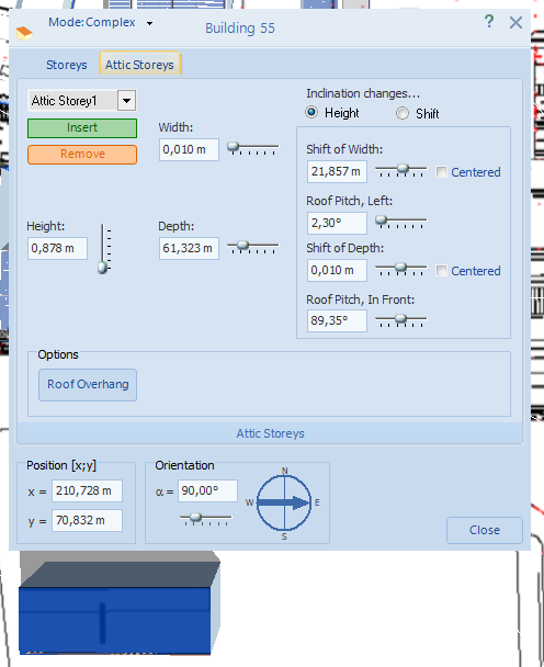
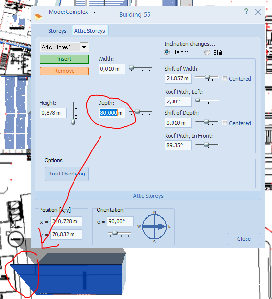
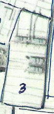
Good morning and happy new year, Is it possible to extrude 3-D objects with inclination from non-rectangular polygons? I have the following building, which has two eaves, one facing east and the other facing west: I see I can extrude a 3-D object but I can only find the option to make it flat and in real life each eave has a 6º inclination. What I have done up to now in similar cases is simply to make a rectangle, extrude that and then not put modules on the parts of the building which don't actually exist. However, that will not work here, as there are other buildings nearby and this one would collide with them if I make it any bigger. Is there a solution for this?
-
OK, thanks.
-
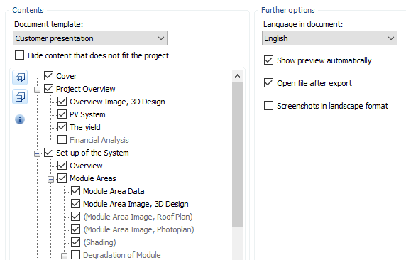
Hi, In my last project I noticed that the legend in the customer presentation was too small, almost unreadable. The room in the box is anyway not used fully, there is a lot of white and what is important is down in a small corner. Is there anyway to make this bigger? In other projects with less info it was bigger but still in a corner... Thanks, Ricardo Last project, unreadable: Another project, OK-ish:


-
Never mind, now it seems to work OK. Thanks again!
-
Hi, Back to this topic, I tried your suggestion and it's not working. Do I need to select any other option? This is what I have: It does show the Overview and the Horizon line (immediately above and below Module areas, also ticked).
-
Great, thanks a lot! Somehow I failed to see that option earlier. Regards, Ricardo
-
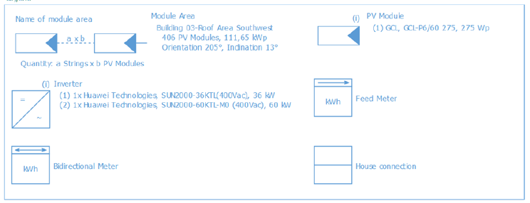
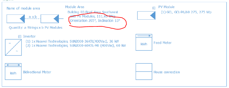
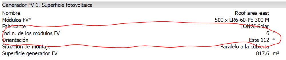
Hi, How do I show module orientation and inclination in presentations for customers? I know it is shown in one of the first pages as an image like this: However, the information there is kinda small and hard to find (you can't Ctrl+F like with the previous PV SOL version). Is there a way to show it in the presentation, something like this? Thanks and regards, Ricardo
-
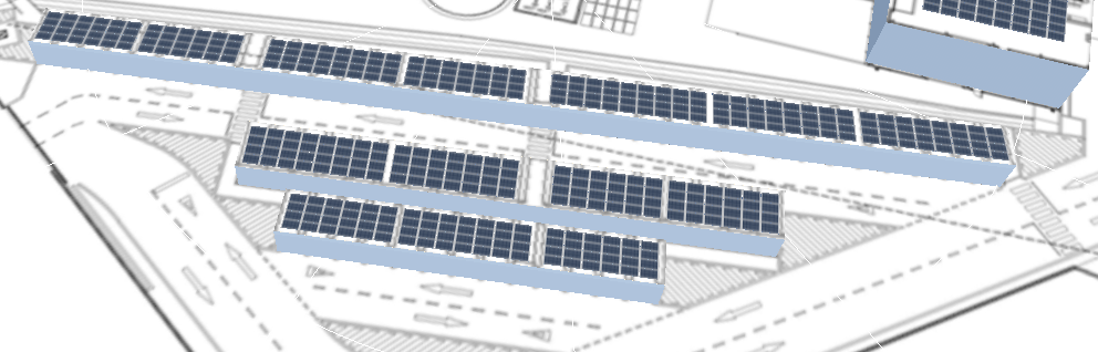
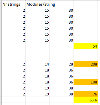
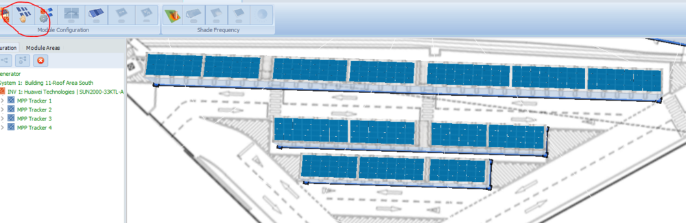
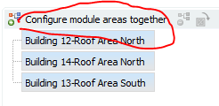
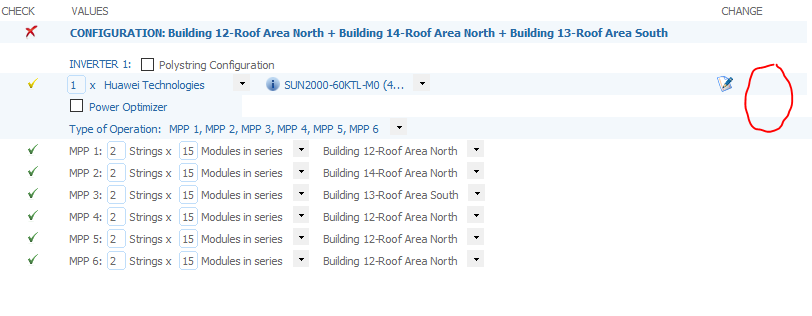
Hi, I have the following 3 roofs, facing north (208 modules) - south (108 modules) - north (76 modules): I would like to configure all 3 of them using 2 Huawei 60 kW inverters, making sure that each MPPT is only connected to modules with identical orientation. That can be achieved with the following configuration: That way, the first roof would be split among the 2 inverters, taking up the first one entirely and then one MPPT from the second one which would have 2 strings of 14 modules each for a total of 208 modules. The second roof would take up 3 MPPTs, each comprising 2 strings of 18 modules for a total of 108 modules; then the last roof would take up the last 2 MPPTs of the second inverter, each with 2 strings comprising 19 modules each, so 76 modules total. I have tried to configure that defining module areas for configuration and configuring module areas together: But when I try that, as I need two inverters with different configurations, I begin configuring the first inverter and then create a new one. Unfortunately, the "copy" function (usually inside the red circlw shown below) is not available: So apparently it is only possible to do this with two inverters if both are configured exactly the same way, which will not work in this case... Can somebody please explain how I could do this?