-
Posts
1,855 -
Joined
-
Last visited
-
Days Won
173
Everything posted by developer_mh
-
err, yes, you're right, sorry. The numbers above don't make sene. The sum of all loan repayments and interests is of course -4552.37 $, excluding the payment of the first year it is -4466.83 $. Then you subtract the normal annual cashflow of 701.79 and you have the -5168.62 $. sorry for the confusion (the explanation was right though ) And yes, I had a typo in the first loan interest rate, it should have been 85.54 $. The loan period is 10 years. Cheers, Martin
-
And I changed the title of your post. Hope that is ok with you
-
Hi Tom, thank you for your question. The Accrued Cashflow minus the pending loans would be your normal cashflow minus all the loan repayments and interests that you still have to pay in future. So, for example: Here I defined a 10 year loan over some 4320 $ with 2 % interest rate and the first 2 years without repayment. If you sum up all loan repayments and interests until year 10, you'll get -5254.16 $. To calculate the Accrued Cashflow minus pending loans for the first year, you'll take the normal cashflow (701.79 $) and subtract the 5254.16 $, but, as you consider the end of the first year, you'll omit the first interest payment of 85.54 $. That is: - 701.79 $ Annual Cash Flow - 5254.16 $ Total loan payments (repayment and interest) + 85.64 $ First loan interest already paid -------------------------------------- - 5168.62 $ Accrued Cahsflow minus pending loans after the first year Hope that helped, kind regards, Martin
-
Dear Tiago, normally, when you start the software, you should see the small window that says that your trail period has expired. You can then click on Register and type in your details, like so: https://help.valentin-software.com/pvsol/2018/start/registration/ If this doesn't help, please let us know! Kind regards, Martin
-
Thanks for the project file! And now I can see the reason why the diagrams are not displayed in your case: You used net metering as economy model, where it does not matter which part of the solar energy is going where and which part of the consumption is covered by which source. In fact, it irritated our customers that were used to the concept of net metering to see these diagrams, so we don't show them anymore if net metering is selected. If you choose 'surplus feed-in' on the economy page, you'll see the diagrams again. Hope that helped. Kind regards, Martin
-
Miraculous! This is obviously not the way it should be... sorry for that! Could you send us the project file, please? I am curious to see what is going on there. You can send it via private message if you don't want to share it with everyone here.
-
ok, this is strange... could you provide a screenshot of the results page, please?
-
Hi Ivan, they are still there, don't worry But you'll have to simulate systems with electrical consumption in order to seem those diagrams. You can choose the according system type on the page "System Type, Climate and Grid". Hope that helps! Cheers, Martin
-
Hi Arbogast, this is a strange error. Seems like your installation is corrupted. Have you tried re-installing it? Kind regards, Martin
-
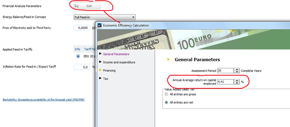
Hi Rogério, the secret is that you'll have to calculate it on a monthly basis in excel. Sometimes you don't have full years in the beginning, e.g. when your PV system is connected to the grid on 01st of September, so we have to all of our financial calculations in PV*SOL based on months. If you want to calculate the IRR in excel, do the following: In our example above we have the investment of 16464.78 $ in the beginning (January of Year 01) and the operating costs of 115.25 $, which gives us -16,579.25 $. From month 02 to month 11 there are no costs or incomes, so you'll write $ 0 there. Then, in December you'll get the income from the feed-in tariff, 1,344.33 $ in our case. The data in your excel sheet will look like this: and so on, for all the years (21 normally). Now, when you calculate the IRR with Excel, =IKV(C5:C256) in our case or =IRR(C5:C256) in the English version, you get a monthly IRR or ROA of 0.368%, which you can multiply by 12 to get the 4.41% annual IRR/ROA. Of course, if you have starting dates other than 01st of January, you'll have to adapt your monthly cash flows accordingly. Hope this helps, kind regards, Martin
-
Hallo Thomas, sehr gute Frage! Da mussten wir auch ein bisschen in unseren Archiven wühlen Die Lastprofile stammen noch aus der Anfangszeit unserer Firma (uns gibt es ja seit 25 Jahren), aber es geht ja nichts verloren.. hier die Quellenangaben Stand 1998, aus dem Handbuch von COPRA 1.0: Zu Quelle 1, eigene Messung: Da unser Unternehmen (damals noch Dr. Valentin Energiesoftware GmbH) in den Anfangstagen auch Energieberatungsprojekte in Zusammenarbeit mit dem damaligen städtischen Energieversorger (Bewag) durchgeführt hat, konnten einige Lastprofile selbst gemessen werden. In der Hoffnung, dass das weiterhilft, beste Grüße, Martin
-
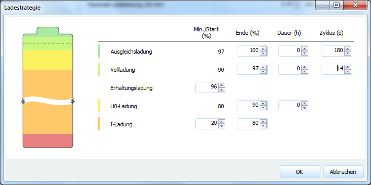
Hallo Florian, wenn wirklich gar nichts mehr aus dem Netz genommen werden soll, müssen die Ladezeiten für die spannungsgeführten Lademodi auf 0h gesetzt werden. Am besten kopierst du dazu erstmal dein jetziges Batteriesystem (zb auf der Batteriesystem-Seite auf den Button 'Detaillierte Auswahl', dann das gewünschte Batteriesystem auswählen und mit dem Button 'Auswahl kopieren' eine Kopie anlegen). Dann unter dem Punkt 'Batteriewechselrichter' auf 'Ladestrategie'. Dort für die Ladedauern der U0-, der Voll- und der Ausgleichsladung 0 eintragen: Damit sind diese Lademodi de facto ausgeschaltet und es kann nicht mehr zu einer Ladung durch das Netz kommen. HIntergrund ist der, dass normalerweise diese Lademodi im oberen Ladezustandsbereich (über 90%) der Pflege und Funktionserhaltung der Batterien und der Batteriebank dienen. Deswegen werden sie auch dann weitergeführt, wenn nicht mehr ausreichend PV-Energie zur Verfügung steht. Dann kommt es für den Rest des Ladevorgangs zur Ladung aus dem Netz. Beste Grüße, Martin
-

geringer spez. Jahresertrag bei Verwendung eines Speichers
developer_mh replied to Goofy's topic in PV*SOL
Hallo Goofy, hier passt ja auch meine Antwort auf deine andere Frage von eben: Mehr zu den Batteriesystemen und deren Verschaltung findest du hier: https://help.valentin-software.com/pvsol/2018/berechnungsgrundlagen/batteriesysteme/ Bei den Ergebnissen in der Energiebilanz finden sich bei Verwendung von DC-Speichern dann auch die Lade- und Entlade-Energien der Speicher. Beste Grüße, Martin -

Vergleichbar geringer spez. Jahresertrag mit E3DC-Systemen
developer_mh replied to Goofy's topic in PV*SOL
Hallo Goofy, ich nehme an, es geht bei den E3DC-Wechselrichtern um die Batteriesysteme in PV*SOL? Diese sind im DC-Zwischenkreis gekoppelt, das heißt, die Energie zum Laden der Batterien wird auf der DC-Seite zwischen PV und PV-Wechselrichter entnommen. Also genau genommen zwischen Mpp-Tracker, Hochsetzsteller und DC/AC-Wandlerstufe, über die dann auch die PV-Energie gewandelt wird. Also geht in diesem Fall die Energie, die zur Ladung der Batterien genutzt wird, von der AC-seitigen PV-Energie ab. Dazu kommt hinwiederum die Energie, die aus den Batterien DC-seitig entladen wird. Daher kann es erhebliche Unterschiede im spezifischen Anlagenertrag geben, wenn man DC- und AC-gekoppelte Systeme (wie einige SMA-Systeme) vergleicht. Beantwortet das die Frage? Wenn nicht, bitte nochmal nachfragen, gerne dann auch mit Angaben zu den verglichenen WR. Danke und beste Grüße, Martin -

zusätzliche Energieerzeugungsanlage über Lastgang importieren
developer_mh replied to Florian's topic in PV*SOL
Hallo Florian, da müssen wir dich leider enttäuschen - negative Lastprofile als Erzeuger sind nicht möglich, auch wenn die Idee einen gewissen Reiz hat Es gibt derzeit auch keine andere Möglichkeit, einen weiteren Erzeuger zusätzlich zur PV zu simulieren. Ein Weg wäre, die Anlage ohn Wasserkraft zu simulieren, ganz normal mit PV und Lastprofil, danach die Stundenwerte zu exportieren und dann in Excel/Calc o.ä. das Erzeugungsprofil des Wasserkraftwerkes gegenzurechnen. Beste Grüße, Martin -
Hi Diego, I will send you a private message with my mail address. Cheers, Martin
-
Hi Diego, I can open the project without any problems. So there must be something that prevents write access to the temporary folders. You could check for example of you have an antivirus software running that prevents PV*SOL from writing to these folders. Or your disc might be full? You could also try to close PV*SOL, go to the temporary folder, in your case C:\Users\diego_000\AppData\Local\Temp\Valentin EnergieSoftware\PVSOL premium 2017) and delete all the randomly numbered folders in there. Hope that helps in solving the problem, kind regards, Martin
-
Hi Diego, would it be possible for you to upload one of your project files that you can't open? You should be able to send them via private message if you don't want to post them publicly. Thanks and sorry for the inconvenience, Martin
-
Hi Michi, ja, tatsächlich, die Berge schlucken schon einiges weg.. dem Panorama nach zu urteilen ist die Bergbahn etwa am Trockenen Steg nähe Zermatt, richtig? Da wird die Einstrahlung tatsächlich sehr anders sein als in Zermatt. Eine Idee wäre noch, wenn Du ein bisschen Recherche- und Excel-Aufwand nicht scheust, bei satelliten-basierten Quellen für die Solarstrahlung zu suchen und die Daten dann in PVSOL zu importieren, nachdem du sie ein wenig überarbeitet hast. Da gibt es mittlerweile ganz gute Webseiten, zb die hier: http://www.soda-pro.com/web-services/radiation/helioclim-3-for-free Hier kann man sich für einen Punkt auf der karte die Strahlungsdaten für 2004 bis 2006 herunterladen. Hab ich mal gemacht für den Trockenen Steg für das Jahr 2005: request_hc3v5lat45.971_lon7.723_2005-01-01_2006-01-01_1850884041.csv Da sind jetzt nicht alle Tage im Jahr vorhanden, da müsstest du manuell schauen, wie du die fehlenden Tage ausgleichst. Evtl sind ja auch die anderen Jahre vollständig. In jedem Fall könntest du daraus dann eine *.dat-Datei machen, die folgendermaßen aussieht: "Trockener Steg" 45.972,-7.721,2939,-1,-30 Ta Gh FF RH 25.9 0 4.2 82.0 26.0 0 3.5 71.5 25.9 0 3.2 67.5 25.8 0 3.5 70.7 … 1. Zeile: Standortname 2. Zeile: Breitengrad, negativer östlicher Längengrad (westlich ist positiv), Höhe über NN, negative Zeitzone, Mittelungsflag (einfach -30 stehen lassen) 3. Zeile: leer 4. Zeile Kopfzeile für Datenreihen, getrennt durch Tab. Umgebungstemperatur in °C, Globalstrahlung horizontal in W/m², Windgeschwindigkeit in m/s, rel. Feuchte in % Ab 5. Zeile: Werte, auch getrennt durch Tab. 8760 Werte untereinander, Punkt als Dezimaltrennzeichen. Die Temperatur, Wind und Feuchte bekommst du auf der gleichen Webseite, aber unter Meteorological Data -> Merra. Damit sollte sich ein realistisches Jahr basteln lassen. Am besten machst du das dann für drei Jahre (noch besser wären natürlich 10, aber so viele Strahlungsdaten gibts da nicht) und mittelst am Ende den Ertrag. Würde mich sehr interessieren, ob das so klappt. Also wenn du es versuchst, lass es mich wissen Beste Grüße, Martin
-
Hi Rogério, the return on assets (or return on investment) in general is your net income (after 20 years normally) in relation to your investments. I think it is best explained with an example (I took the example project "photoplan.pvprj"). In the results you have, amongst others, these figures (the important ones are bold): System Data Grid Feed-in in the first year (incl. module degradation) 10.966 kWh/year PV Generator Output 11,8 kWp Start of Operation of the System 01.01.2017 Assessment Period 20 Years Economic Parameters Return on Assets 4,41 % Accrued Cash Flow (Cash Balance) 9.346,78 $ Amortization Period 13,4 Years Electricity Production Costs 0,08 $/kWh Payment Overview Specific Investment Costs 1.400,00 $/kWp Investment Costs 16.464,00 $ One-off Payments 0,00 $ Incoming Subsidies 0,00 $ Annual Costs 115,25 $/year Other Revenue or Savings 0,00 $/year So, you invested 16464 $ in your PV plant, and after 20 years you have an acrrued cash flow of 9346.78 $. You have a return on assets (ROA) of 4,41 %, which you can think of as the virtual interest rate that you would have needed if you gave your investment (16464 $) to a bank for 20 years in order to get a total of 25810.78 $ (16464 + 9346.78 $). In other words, if you decided not to build the PV plant but invest your money in an asset with some interest rate, you would have needed an interest rate of 4,41 % to get the same net income in the end as with you PV investment. In our online help you'll find the formula for the cash value for more detail. This symbolizes the value of your assets in comparison to an investment in a bank account with a fixed intereset rate. If your cash value after 20 is 0 it means that you have the same ROA from your PV investment than you would have on a bank account for a given interest rate. And that is the way the ROA is actually calculated: In the fomula of the cash value you put in a interest rate (q), you get a cash value of xx, you put in a higher interest rate, you get a smaller cash value and so on, until the cash value is 0. The interest rate you have then is the ROA. That means, if you put in the 4,41 % as your return on capital, like so: you get an accured cash flow of approx. 0 $ after 20%: Economic Parameters Return on Assets 4,41 % Accrued Cash Flow (Cash Balance) 145,86 $ Amortization Period More than 20 Years Electricity Production Costs 0,12 $/kWh I hope this helped. If not, please don't hesitate to ask! Kind regards, Martin
-
Hi Yaroslav, of course you can! You'll need module mounting systems for this which allow for any orientation you could think of. Perhaps this short video might answer your question already: If not, please let me know. Kind regards, Martin
-
Hallo Michi, interessante Frage! Hochgelegene Standorte realistisch nachzubilden, ist wegen der speziellen klimatischen Bedingungen tatsächlich sehr komplex. Gerade das Mikroklima hat einen sehr starken Einfluss in den Bergen und kann bewirken, dass zwei nur wenige hundert Meter voneinander entfernte Standorte völlig unterschiedliche Einstrahlungswerte übers Jahr aufweisen (zB eine exponierte Lage nahe dem Gipel im Vergleich zu einer schattigen, niedrigeren Lage auf der Wetterseite). Daher sind in solchen Fällen Messdaten vom späteren Standort Gold wert. Da man diese in der Regel jedoch nicht hat, wirst du dich mit einer Abschätzung über den nächstgelegenen Standort begnügen müssen. In jedem Fall kannst du aber versuchen, zumindest über die Albedo (Reflexionseigenschaften des Bodes) und die Horizontverschattung die Begebenheiten vor Ort möglichst realistisch einzugeben. Für die Albedo solltest du Werte um die 0.8 für die Monate, in denen es Schnee gibt, eingeben, sonst die standardmäßigen 0.2. Die Horizontverschattung sollte auch möglichst genau ermittelt und dann bei den Modulfächen unter Verschattung als Azimut/Elevations-Datenpunkte eintragen. Ich hoffe, das hilft erstmal weiter. Wenn du weitere Fragen hast, bitte gerne immer Guten Start in die Woche, Martin
-
Hi Boris, Yes, of course this possible! Am I right that you refer to the planning in the 3D environment? If so, just select the modules you want to connect (by using the left mouse button and holding the Ctrl key), right click on your selection and choose "Add to 'Define Module Areas' Dialog". Then you can go to the dialog "Define Module Areas" by clicking the third button at the top left. In the dailog you will see your selected modules with the option to connect them to an inverter. If you want to define other module areas first, e.g. for connecting two module areas to one inverter, just close the dialog, define another module area in the same way as before, and re-open the dailog. Then you'll have the two areas available to connect them. I hope I could answer your question. If not, please dont hesitate to ask. Best wishes and kind regards, Martin
-
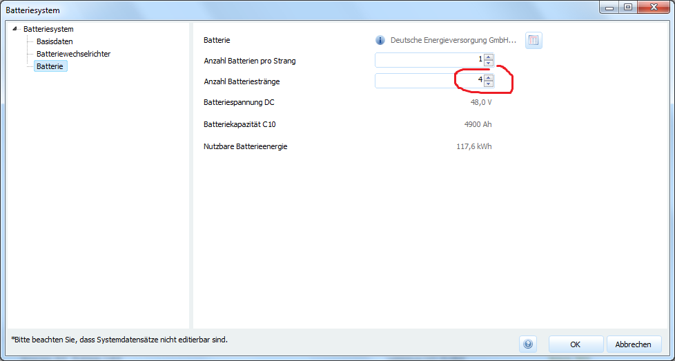
Hallo PNK, Hinweis: Bitte den letzten Post mit aktuellen Informationen beachten. eine Anzahl kann man bei den Speichersystemen leider derzeit nicht eingeben. Was Sie aber machen könnten, wäre die Anschlussleistung des Speichers sowie die Anzahl der Batterie-Stränge zu vervierfachen. Dazu kannst du einfach eine Kopie des Senec-business 30Pb anlegen und die folgenden Felder anpassen: So kann man so tun, als hätte man eine 4er Kaskade des Systems. Hilft das weiter? Beste Grüße und viel Erfolg, Martin
-
Hallo Valentin Kunkel, bitte entschuldigen Sie die späte Antwort. Könnten Sie uns vielleicht das Projekt zur Verfügung stellen? Dann könnten wir besser nachvollziehen, wie die Werte zustande kommen.Gerne auch als private Nachricht. Danke! Beste Grüße, Martin


