developer_mh
-
Posts
1,855 -
Joined
-
Last visited
-
Days Won
173
Everything posted by developer_mh
-
Hallo Dirk Mayer, Hinweis: Bitte den letzten Post mit aktuellen Informationen beachten! ein Anwender der ersten Stunde! Das freut uns natürlich sehr - und lässt uns nostalgisch an die Zeiten von Installationen denken, die noch auf mehreren Disketten ausgeliefert wurden Wobei das zugegebenermaßen vor meiner Zeit bei Valentin war. Meinen Sie den Batterie-WR von SolarEdge (StorEdge)? In diesem Fall müssten Sie dieses Gerät selbst in der Datenbank anlegen: Gehen Sie im Menü auf Datenbanken -> Batteriesysteme (netzgekoppelt) Der Einfachheit halber wählen Sie sich das System mit SMA Sunny Island + LG Chem Speicher, der dem entspricht, den Sie verwenden wollen, z.B. "SMA Sunny Island 6.0H-11 Set - LG Chem 5,0 kWh" Kopieren Sie das System (Rechtsklick -> Kopieren) Wählen Sie für das Unternehmen nun SolarEdge aus der Liste aus Benennen Sie das Modell um (z.B. StorEdge - LG Chem 5,0 kWh) Auf der Seite "Batteriewechselrichter" geben Sie die Leistungsdaten ein, die Sie dem Datenblatt entnehmen können Bestätigen Sie mit 'OK' und das neue System wird gespeichert. Ich hoffe, dass das Ihre Frage beantwortet. Wenn nicht, einfach nachfragen Beste Grüße, Martin
-
Hi Boris, we are very sorry about what happened to your hdd. At least, you won't have a problem concerning PV*SOL. The official way to recover your licence is to fill out the form "Request for reactivation of software" which you find here: http://www.valentin-software.com/en/downloads/other You can send this form to sales@ or info@valentin-software.com (or even fax it to us ) All the best for the recovery of the rest of your system! Kind regards, Martin
-
Hello Mehmet Senol, edit: Please see the next post with updated information at the moment it is not easily possible to create BTS towers or in general any objects with lattice structure. What I would recommend would be the following: 1) Make a solid tower like you did and simulate your project, so that you can see the energy yield of your system. This will be your worst case. 2) As a best case, delete this tower and simulate again. 3) As a further approximation you could create four very thin poles (use the chimney object) and place them in the corners of a square with the dimensions of the BTS tower. Simulating this kind of shading object will give you an energy yield that lies between your best and your worst values. The real shading losses will be a bit higher than the value of simulation 3), but lower than simulation 1). But it is good point, we will consider introducing this kind of shading object in the further. Thanks for that! Kind regards, Martin
-
Hello Rob, the usage factor determines how close the tracking systems are placed to each other. A usage factor of 1 means, that the distance of one tracker to the next is as long as the module width. The distance is measured from the center of one tracked module to the center of the next. So, a usage factor of 0.5 would indicate that the distance between one module and the next is twice the module width. This factor mainly influences the backtracking behaviour. If modules are very close, they have to be tracked back earlier than modules that have a longer distance between them. Hope that helps. If you have any further questions, please don't hesitate to ask. Kind regards, Martin
-

Pvsol Premium - Unterschied/mehrwert Im Vergleich Zu Pvsol (Normal)
developer_mh replied to Planer's topic in PV*SOL
Hallo Planer, der Hauptunterschied liegt in der Möglichkeit, in PV*SOL premium Anlagen in einer 3D-Visualisierung planen zu können. Dadurch lassen sich z.B. Verschattungsverluste präzise analysieren, etwa durch nahestehende Bäume, Dachaufbauten, andere Gebäude etc. Außerdem können Sie dort auch Leistungsoptimierer wie zB SolarEdge verwenden. Sie können des Weiteren Verschaltungen optimieren, Kabelpläne erstellen, Schattenverläufe visualisieren usw usf. Sie können dann natürlich auch schöne Ansichten Ihrer Planung erstellen und dem Kunden präsentieren. Bevor Sie sich entscheiden, können Sie natürlich auch einfach PV*SOL premium herunterladen und 30 Tage lang kostenlos testen. Hier finden Sie den Download: http://www.valentin-software.com/produkte/photovoltaik/57/pvsol-premium Beste Grüße, Martin -
Hallo UserEH, danke für die Nachfrage. Wenn die Messung vorliegt, können Sie den Winkelkorrekturfaktor ermitteln, indem Sie sich den Wert bei einem Einfallswinkel von 50° anschauen. Dieser entspricht dem Wert, der im Moduldaten-Dialog auf der Seite "Weiteres" als Winkelkorrekturfaktor eingetragen werden muss. Beste Grüße, Martin
-
Hallo Sigma, Insel-Systeme kann man erstellen, indem man in der Anlagenart-Auswahl (auf der Seite "Anlagenart, Klima und Netz") die netzautarken Systeme wählt. Dabei haben Sie die Wahl zwischen Systemen mit oder ohne Backup-Diesel-Generator. Beste Grüße, Martin
- 1 reply
-
- 1
-

-
Hi Julian Ayala, I think the easiest way to accomplish that would be to select one computer to collect all the from-grid tariffs from the other computers and then distribute the database manually across all computers in your company. To do that you would have to do the following: Make sure that every computer in your company uses the same version of PV*SOL premium. On each computer that has from-grid tariffs that you want to copy, you would create a project that contains the from-grid tariff in question, save it and open it with PV*SOL on the one "master" computer After you finished this step for all the computers, you have one database on the master computer that contains all from-grid tariffs from your team Now you can copy the database ("C:\ProgramData\Valentin EnergieSoftware\PVdatabase\Version4.0\PVSOL.sdf", or if you use PV*SOL older than the new version it would be database version 3.5, so "C:\ProgramData\Valentin EnergieSoftware\PVdatabase\Version3.5\PVSOL.sdf" ) to all the other computers in the same directory. That way each computer has the same database. CAUTION: if the users in your company have custom pv modules, inverters or the like in their database, you would overwrite them this way. If you do not want to lose those custom db entries, you would also have to include them in the projects that you copy from one computer to the other. For the future, if you want to be able to create the tariffs on one computer and use them on the others, I think the easiest way would be to include the new tariff in a project, send it to your colleagues, let them open it and thats it. I hope that helps. If have any further question, please do not hesitate to ask. Kind regards, Martin
-
Export Der Simulationsergebnisse In Minütlicher Auflösung
developer_mh replied to JK1900's topic in PV*SOL
Hallo JK1900, um die Simulationsergebnisse in Minutenauflösung zu sehen, müssen sie auch die Klimadaten in Minutenauflösung rechnen. Andernfalls wird die PV-Anlage in stündlichen Schritten berechnet und nur nachgeschaltet die Verbraucher (und deren Deckung, sowie Netzbezug oder Einspeisung) in Minutenwerten. Die Minutenauflösung für die Klimadaten können Sie auf der Seite "Anlagenart, Klima und Netz" unter "Klimadaten" und dort über den Link "Simulationsparameter" einstellen. Die Option heißt "Mit synthetisierten Minutenwerten der Einstrahlung simulieren". Hoffe, das hilft weiter, viel Erfolg noch, Martin -
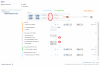
Hi Rob, edit: See updated information for PV*SOL premium 2018 in the post below in the "module configuration tab" you can select the option "configure all unconfigured modules". There you can choose e.g. SolarEdge Power Optimizers as inverter, have them automatically connected to your modules (one po to one module), then click "OK", go back to 3D environment, and then set the power optimizer star in the overview on the left. Hope that helps, Martin
-
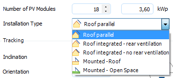
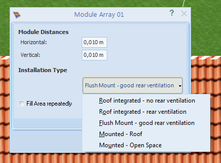
Hi Rob, thanks for the question. There is a little translation difference of the 3D and 2D versions of the installation type. We will have to fix that. In 3D, flush mount refers to the roof parallel installation type in 2D. For reference, here is an excerpt from the help [Flush mount in 3D] Roof parallel, if the modules are mounted a distance above the roof cladding. Roof integrated - rear ventilation if the system will be installed on a support structure parallel to the roof cladding. Rear ventilation helps to cool the modules and thus higher performance. Roof integrated - no rear ventilation if the module forms the roof cladding. Mounted - roof, if the modules are mounted directly on the roof. Mounted - open space, if the modules are mounted at ground level. And the two drop-downs in action: 2D: 3D: So, to answer your question, for a normal roof mounted system that is installed parallel to the roof surface, but on a mounting system, you would select flush mount in 3D and Roof parallel in 2D. If you have, say, a roof of an industrial hall where you place your tilted mounting systems on, you would choose Mounted - roof. Additional info: Behind those installation types there are thermal coefficients with which we feed our thermal module model. Here is the respective table from our help (in the chapter basis of calculation): Table 1: The heating DT with respect to the outside temperature is, for example, with irradiance ESTC = 1000 W/m² DT Installation Type 29 K Roof parallel 32 K Roof integrated - Rear ventilation 43 K Roof integrated - No rear ventilation 28 K Mounted - Roof 22 K Mounted - Open Space Source: DGS Guide to Photovoltaic Systems, 3rd edition Hope that helps, kind regards, Martin

-
That's good to hear, jakoz.
-
Hi jakoz123, that is an unusual behaviour you are reporting. Could you tell us the specifications of both computers (with graphic card information), as well as the list of installed modules that you can find under Help -> Info -> System, also for both installations. Perhaps we can see something there. If you don't want to post your information publicly here, you can also send me a PM. Thanks and kind regards, Martin
-
Hallo segelgras, um Polygone zu löschen, gibt es zwei Möglichkeiten: entweder in der Übersicht links markieren, dann rechts klicken, dann auf "Entfernen". oder direkt in der 3D-Ansicht markieren, rechts klicken und auf "Entfernen". Ich hoffe das hilft weiter, beste Grüße, Martin
-
Hallo Erwin, nein, leider ist das derzeit nicht möglich. Ist aber ein interessanter Punkt, den ich mal mit meinen Kollegen besprechen werde. Momentan kann man einen Speicher definieren, der AC-seitig mit der Anlage, den Verbrauchern und dem Netz verbunden ist. In der nächsten Version werden dann übrigens auch DC-Speicher in Generator- (zwischen PV-Fläche und WR) oder Zwischenkreis-Kopplung (im DC-Zwischenkreis des Wechselrichters) verfügbar sein. Beste Grüße, Martin
-
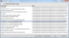
Hi jakoz123, right now you have the possibility to design and simulate your PV plants with SolarEdge Power Optimizers. As you might have seen, we have listed several models of SolarEdge devices in our inverter database: The combination of power optimizers and inverters of SolarEdge is not yet possible, but we are working on a solution for the future. This will include all module or substring level electronics and their electrical connection. Kind regards, Martin

-
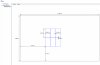
Dear Esteban, the solution to your problem lies in the inverter you have chosen. The new model by RefsuSOL Inc has a smaller voltage range than the older model distributed by REFU Elektronik GmbH. When you choose the older model, you can connect the modules as you would expect. See the screenshot: Also, I attached a project that corresponds to the schematics of the older version of PV*SOL that you provided. Kind regards, Martin RefuSol 4x20 Phono PS250P20U.pvprj
-
Hallo Phlix, auf der Seite 'Verbraucher' unter 'Neuer Verbraucher' gibt es drei Möglichkeiten, neue Verbraucher hinzuzufügen: Lastprofil laden und importieren: Dort hast du wahrscheinlich geschaut. Da sind alle neueren und höher aufgelösten Lastprofile zu finden (in 1min- und 15min Auflösung). Außerdem kann man dort auch eigene Lastprofile importieren Lastprofil definieren: Das ist der alte Dialog für die verbraucher, mit dessen HIlfe man eigene Lastprofile sehr flexibel zusammenstellen kann. Hier gibt es auch vorgefertigte Verbrauchsprofile: Man geht auf den vorgewählten elektrischen Verbraucher, dann auf 'Verbrauchsprofile' und dann unten auf 'Laden'. Da gibts nochmal ne Menge Lastprofile, auch zwei Schulen. Die dritte Option ist zur Definiition von Einzelverbrauchern, wie zB Kühlgeräten, Pumpen oder dergleichen. Man kann natürlich auch mehrere Lastprofile und Lastprofilarten kombinieren. Viel Erfolg bei der BA, Martin
-
Hallo Paolo, danke für die Fragen zu dem hochaktuellen Thema! zu 1) die Simulation von bifazialen Modulen ist derzeit noch nicht möglich. Sie werden ganz normal wie einseitige Module simuliert und weise dementsprechend keinen Mehrertrag auf, das ist richtig. Wir sind an dem Thema dran und werden es zu gegebener Zeit implementieren, aber da das Thema und vor allem die Produkte noch relativ jung sind, fehlen uns derzeit noch verlässliche Daten, um dafür Modelle zu entwickeln. zu 2) Momentan gibt es in der Berechnung der Strahlungsgewinne durch Bodenreflexion (wo der Albedo seine Rolle spielt) keine Unterschiede in unserer Simulation, da wir die bifazialen Module ja noch nicht implementiert haben. Die Rückseite der Module wird zur Zeit als optisch und elektrisch inaktiv angesehen. Wenn wir das Modell für die bifazialen Module dann einbauen, wir des aber natürlich so sein, dass auch die Reflexion der Solarstrahlung auf die Modul-Rückseite mit berücksichtigt wird. Beste Grüße, Martin
-
Hallo Dani, in Ergänzung noch zum GAK: Es stimmt schon, dass man sie nicht manuell definieren kann, aber sie definieren sich sozusagen von selbst. Wenn man zB eine Verschaltung hat mit 3 Strängen à 4 Modulen an einem MPP-Tracker und dann auf der Seite "Kabel" in die detaillierte Auswahl geht, sieht man, wie die Stränge vor dem MPP-Tracker des Wechselrichters mit einem GAK zusammengefasst werden. In diesem Fall hätte man 3x2 Eingänge und 1x2 Ausgänge: Ich hoffe, das hilft noch ein bisschen weiter. Ansonsten wären wir daran interessiert zu erfahren, welche Funktionalität und/oder Anwendungsfälle Sie beim GAK noch brauchen. Beste Grüße, Martin
-
When I replace my 'Bemassungsplan1.xml' with yours, it works: So, honestly, I don't have an idea right now what could be the problem. I will have to discuss this with my colleagues next week. The only thing left that comes into my mind is that perhaps an anti-virus software or other kind of program that scans your hard drive is preventing access to the file. So if you have an application like this, try disabling it for a while and see if it works. If not, we will have to discuss further possible solutions next week. Sorry for the inconvenience caused. Kind regards, Martin
-
ok. Could you send me the contents of the file please? You can paste it here or you can send it via private message.
-
Ok, so could you check the following please: The folder C:\Users\[your user name]\AppData\Local\Temp\Valentin EnergieSoftware\PVSOL premium 2016\ should contain folders like '18113737351' and so on. These are temporary folders for your projects while you work on them. When you start a new 3D project and you go into the 3D environment, there must be a folder called 'Visu3D' inside the newest of these numbered folders (but ignore the folders with T at the end). And once you come back from the 3D environment with a valid and connected pv system, there should be a file called 'BemassungsPlan1.xml' inside 'Visu3D'. Could you please tell me if this is the case for you?
-
Thanks a lot for providing the screenshots. This is a strange behaviour you encouter there. Just to make sure that your project file itself is not the reason: Does this also happen if you start a new test project, go into 3D environment, design a simple PV plant, connect it and all, go back to the main program (adopting the changes of course), and then go to the plan page?
-
Hey jerryg, for the roof layout you can go to the plan page after returning from the 3D environment. There you'll find all your dimensioning plans for your roofs which you can export to dxf or pdf (from Din A4 to Din A0). For the cabling plan you can set the number of Din A4 pages on which to draw the plan. So if you want detailed output you could choose e.g. 2 by 2 pages and the plan will be scaled accordingly. The plan will be attached to your project presentation on the last page of our main program. Hope that helps, kind regards, Martin