-
Posts
1,855 -
Joined
-
Last visited
-
Days Won
173
Everything posted by developer_mh
-
Hallo PV-Flow, leider kann man derzeit in PV*SOL nur einen GAK pro MPP-Tracker festlegen. Die DC Hauptleitung, die bei dir unterschiedliche Längen und Querschnitte haben, würden somit in PV*SOL zu einer zusammengefasst. Aus pragmatischen Gründen würde ich empfehlen, einmal den worst case zu rechnen (alle Leitungen haben 115m und 50mm² Durchschnitt), und einmal den best case (56m und 120mm²). Für beide Fällen schaust du dir in der Energiebilanz hinten bei den Ergebnissen die Kabelverluste an. Dann kannst du einschätzen, in welchem Rahmen sich das bewegt. Dann würde ich am Ende eine Länge und einen Querschnitt nehmen, der näher am worst case ist, aber das Ergebnis auch nicht zu sehr verzerrt. Beste Grüße, Martin
-
Hallo Rübezahl, kannst du einen Link schicken, auf welche FAQ du dich beziehst? Ich vermute, dass hier ein Missverständnis vorliegt, die Modulneigung wird in jedem Fall mit in die Ertragsberechnung einbezogen, sie ist essentiell. Meinst du diesen Eintrag hier? Hier geht es um die resultierende Modulneigung und -ausrichtung, wenn aufgeständerte Anlagen auf schiefen Ebenen platziert werden, da sich deren Neigungs- und Ausrichtungswinkel überlagern. Beste Grüße, Martin
- 2 replies
-
- modul
- neigungswinkel
-
(and 1 more)
Tagged with:
-

Hybrid PV system - DC/AC inverter + DC/DC regulator + Diesel generator
developer_mh replied to RicardoM's topic in PV*SOL
Hi RicardoM, sorry for the late reply. There is no way right now in PV*SOL to add DC loads or DC/DC converters. Other than that, the system you showed in the diagram looks strongly like the one you selected (we developed the offgrid part of PV*SOL together with SMA some years ago), except for the DC loads of course. Even the housing of the bidirectional battery inverter looks like the SMA Sunny Island Could you tell me which device this is? Do you have information how the energy flow is managed? Kind regards, Martin -

Probleme bei Batteriespeicher von Solarwatt MyReserve
developer_mh replied to ElektroFreitag's topic in PV*SOL
Hallo ElektroFreitag, momentan lassen sich DC-gekoppelte Batteriespeicher, wie das SolarWatt-System eines ist, immer nur mit einem PV-Wechselrichter verbinden. Wir sind uns der Einschränkungen bewusst und haben das als Feature- / Weiterentwicklungswunsch schon auf der Liste. Allerdings noch nicht terminiert, also können wir leider noch nicht sagen, wann das Feature verfügbar sein wird. Beste Grüße, Martin -
Hi Jack, thank you for sending the project files. I can confirm that I see the same behaviour. There seems to be a bug when using module mounting systems with an inclination of 0,01° and module numbers of above 4 or 5. I think the root of the problem is that the module mounting systems are not used in the way we intended. If you want to place modules parallel to roof, consider to place them directly on the roof using the "module coverage" mode instead of using mounting systems. See more here: https://3d-help.valentin-software.com/pvsol/en/#t=html%2Fen%2F3d%2FEinfuehrung_in_die_Modulbelegung.htm There the bug doesn't effect you, and you can also work faster and more flexible. I configured one of the projects that you sent me in this way to demonstrate what I mean. I will send it to you by private message. I hope this helps, kind regards, Martin
-

Krüppelwalmdach wird von PVsol in Teilflächen zerlegt
developer_mh replied to Ralf's topic in PV*SOL
Hallo Ralf, hallo GeromeK, ja, das stimmt natürlich, über die Grenze hinweg lassen sich dann keine Module legen. Ein entsprechendes Dach fehlt in den Vorlagen, auch das ist richtig. Die Alternative wäre, wie bereits erwähnt, ein Satteldach mit den Sperrflächen zu versehen. Zur Präsentation beim Kunden könnte man, wenn die Sperrflächen optisch nicht gefallen, z.B. auf Photo Plan zurückgreifen. Die Variante mit dem 2D-Dach scheint mir in diesem Fall keine geeignete Alternative zu sein, da hier gegenüber der Variante mit dem Satteldach und den Sperrflächen ja nichts gewonnen ist. Beste Grüße, Martin -

Krüppelwalmdach wird von PVsol in Teilflächen zerlegt
developer_mh replied to Ralf's topic in PV*SOL
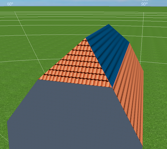
Hallo Ralf, Krüppelwalm-Dächer werden bei uns immer in zwei Segmente unterteilt, da die entstehenden Dachflächen nicht zwangsweise den gleichen Neigungswinkel haben. Hier z.B.: Man kann aber natürlich trotzdem beide Teil-Dachflächen belegen und dann gemeinsam elektrisch verschalten, indem man im Reiter "Modulverschaltung" auf "Alle unverschalteten Modulflächen verschalten" klickt. Dann mit gehaltener Strg-Taste beide Modulflächen selektieren, auf "Modulflächen gemeinsam verschalten" und dann wie gewohnt verschalten: Ich hoffe, das hilft weiter. Beste Grüße, Martin -
Hi Sebastian, sorry for the late answer, I think we overlooked it and forgot to reply. The data that is displayed in the carpet plots is identical to the data in the time series. So you just have to select the according time series, eg. "Irradiance onto horizontal plane", choose the full year as time period and then right click and export it to Excel. Hope that helps, kind regards, Martin
-
Hi Alisson, it seems that the picture that you attached is not there. Could you try and upload it again? Kind regards, Martin
-
Hi Jack, thank you for reporting this strange behaviour. Could you send us a project file so that we can reproduce the issue. You can also send it by private message here in the forum, so that it doesn't become public. Kind regards, Martin
-
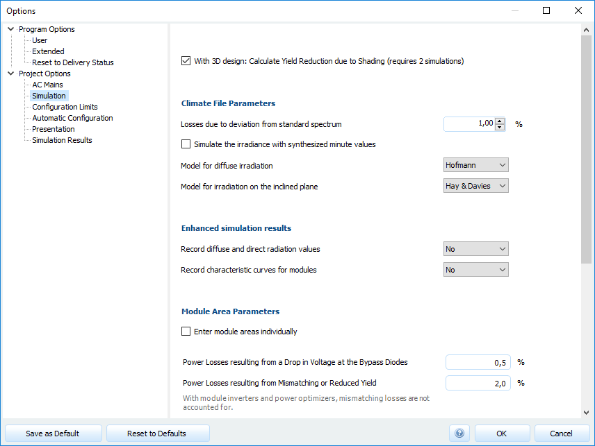
Dear Bulent, thank you for your question. In PV*SOL, we use climate data from the well-known climate data specialist Meteonorm, see here: https://help.valentin-software.com/pvsol/2019/calculation/irradiation/climate-data/ PVsyst also uses Meteonorm, so in terms of irradiation data there shouldn't be any difference between PV*SOL and PVsyst. Do you have an example project where we can see PVsyst and PV*SOL energy yields side by side? Often the differences in the energy yield come from the models that are used to calculate the irradiance on the tilted plane of the PV modules. These models can be modified in the program options under Options -> Program Options -> Project Options -> Simulation: Regarding values from SolarGIS: Yes, it is not unusual that climate data values can vary within +- 15 % between the sources. SolarGIS uses mainly satellite data, if I remember correctly. Meteonorm uses mainly ground measurement stations in combination with satellite data. And then there is PVGIS which also uses satellite data and whose values differ both from SolarGIS and from Meteonorm. See some details about the meteorological approaches here: SolarGIS: https://solargis.com/docs/methodology/solar-radiation-modeling Meteonorm: https://meteonorm.com/assets/downloads/mn73_theory.pdf PVGIS: https://re.jrc.ec.europa.eu/pvg_static/pvgis5.pdf As you will soon realize, there is no true or false for climate data. Nor is there any "higher values are better". It depends on what you want to achieve. If you want to achieve a higher simulated energy yield than your competitor, yes, you might be willing to choose the data source with the highest irradiation for a given place. But what happens if this simulated energy yield is too high? Won't the customer be dissappointed? We think that on the long run, it will shed a negative light on the project planners and users of our software (and the whole industry), which is why we always try to provide simulations that are conservative, but still realistic. The climate data of Meteonorm do fit nicely in this "conservative" concept, where the yield that we simulate is nearly always topped in reality. But of course, you are free to import any other climate data into our software and simulate with that. A guide how to import climate data from other sources can be found here: https://help.valentin-software.com/pvsol/2019/pages/system-type-climate-and-grid/meteosyn/#options Hope that helps, kind regards, Martin
-
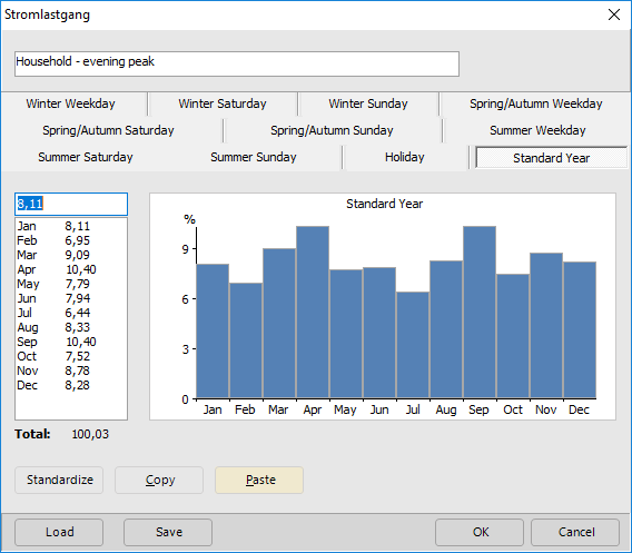
Here is the excel sheet, you can just paste your monthly values into the green fields and copy the blue fields to the clipboard PVSOL Modify Monthly Consumption Percentage Before Import.xlsx
- 5 replies
-
- consumption
- load
-
(and 2 more)
Tagged with:
-
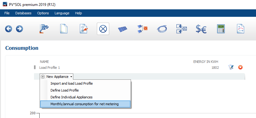
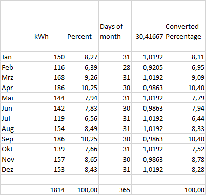
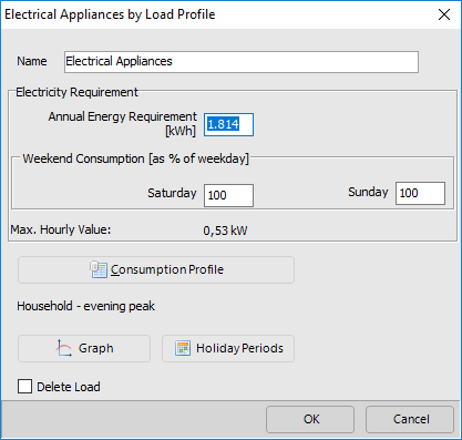
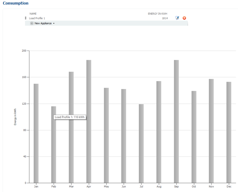
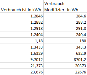
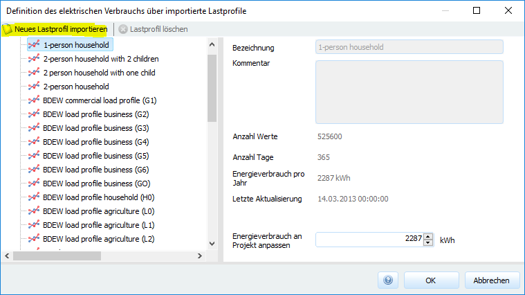
Hi Tim, you are right, the import of the 12 monthly values in the dialog you posted in your first post are not accurate. This is a bug we know of quite some time, but this section of our software is/was a remainder from older times This is one of the reasons why we refurbished these old components now. In the next major release (which is planned for early 2020), an update of the consumption dialogs is included. In the meantime, if you work with net metering you can enter the monthly consumption values directly here: Or, if you are willing to modify the monthly consumption before importing them, you can do the following: Import the monthly energy values in kWh and calculate the monthly percentage (first two columns) Calculate the monthly modification factor with (days of month) / (365/12) Calculate the converted percentage with (real percentage) / (modification factor) then you can select the last column, copy it to the clipboard and paste it into the dialog that you showed Then click ok and enter the yearly energy consumption here Then you'll get the monthly energy consumption into PV*SOL as desired: Hope that helps, and sorry for the circumstances. Kind regards, Martin
- 5 replies
-
- consumption
- load
-
(and 2 more)
Tagged with:
-
Hi Glenn, in addition to my colleague's comment I'd like to add that in our current PV planning software PV*SOL premium 2019 you'll find all the features that were available in the SMA Offgrid Configurator as well, and lots more. See here for a features overview: https://pvsol.software/en/features-pricing or https://www.valentin-software.com/en/products/photovoltaics/57/pvsol-premium You can also test these applications for free for 30 days. Kind regards, Martin
-
Hallo Ralf, ja, diese Erweiterung steht bei uns auf dem Zettel. Terminlich können wir dazu zwar noch nichts sagen, aber wir arbeiten dran. Beste Grüße, Martin
-
Hallo OD111, eine Möglichkeit wäre, eine Art Projekt-Vorlage zu machen und diese bei jedem neuen Projekt zu laden. Dazu einfach das gewünschte Lastprofil auswählen und das Projekt unter einem aussagekräftigen Namen speichern, z.B. "Projektvorlage - Verbrauchsprofil Einfamilenhaus Mitteleuropa.pvprj". Das kannst du in Zukunft dann zu Beginn eines neuen Projektes laden, dann direkt unter einem neuen Namen speichern ("Speichern unter" -> aktueller Projektname) und dann weiterarbeiten. Beste Grüße, Martin
-
Hallo Tobi, Welche Module sind denn nicht korrekt in der Datenbank? Bei uns geben ja die Hersteller die Daten ein insofern können wir leider nicht jederzeit garantieren, dass alle Daten korrekt sind. Aber wenn wir wissen, um welche Module es sich handelt, können wir das den Herstellern so weitergeben. Ansonsten hast du das richtig gemacht. Das Modul kopieren, einen Leistungsoptimierer auswählen und die restlichen Eingaben so stehen lassen. Die Warnung bezüglich der Mismatching-Verluste kann man wahrnehmen und dann je nach Anwendungsfall ernst nehmen oder ignorieren Es entstehen durch unterschiedliche Stanglängen auf jeden Fall Mismatching-Verluste, dessen sollte man sich bewusst sein. Es empfiehlt sich auch, diese nach der Simulation in der Energiebilanz zu überprüfen. Aber wenn man sich dessen bewusst ist, und diese Verluste in Kauf nimmt, kann man die Warnung ignorieren, ja. Tutorials würden wir sehr gerne mehr machen, momentan fehtl uns leider ein wenig die Zeit dazu. Aber wir nehmen deine Anregung auf, danke dafür. Beste Grüße, Martin
-
Hi Niclas, yes, I think it has nothing to do with the PV*SOL version. Have you imported this exact file before and it worked? Or was it another file? Did you change anything else in your system? Kind regards, Martin
-
Hi Niclas, can you check if there is another process accessing these directories? E.g. do you have an antivir software where you could add an exception for that folder, just to test? Kind regards, Martin
-
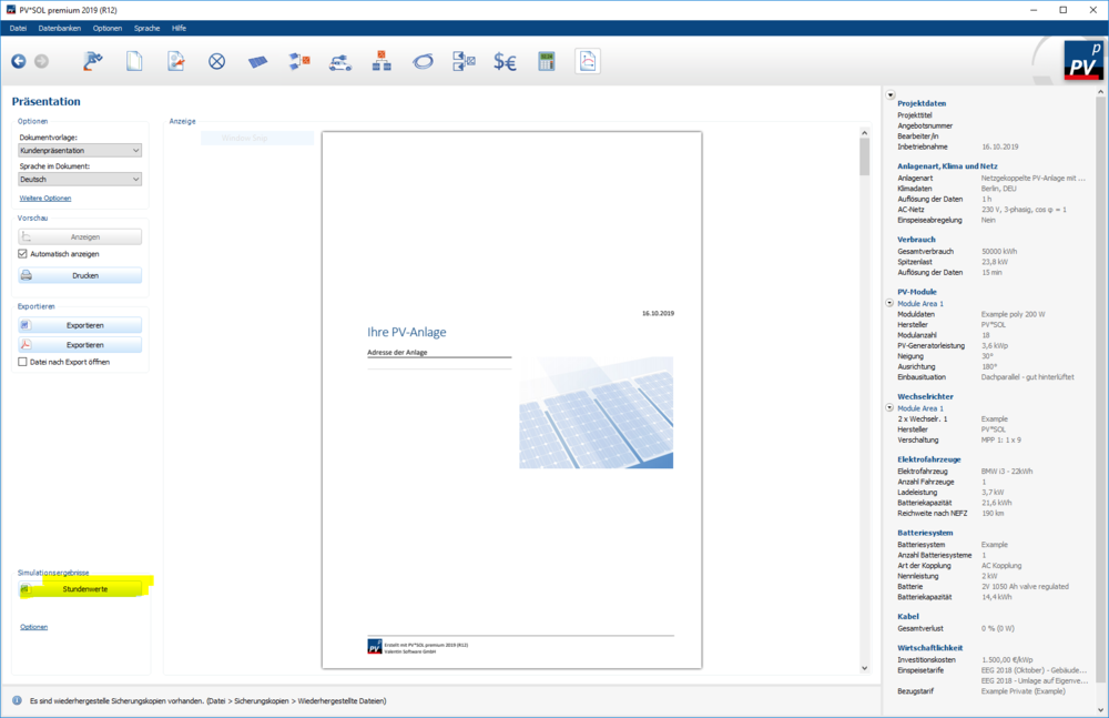
Hallo J.Ackfeld, leider haben wir momentan keine "saubere" Lösung, um BHKW in PV*SOL zu simulieren. Eine unsaubere, aber ggfs. gangbare Lösung wäre, den Verbrauch um eine Grundlast von 10 kW zu reduzieren, wenn das das derzeitige Lastprofil überhaupt hergibt. Das ginge nur, wenn beim derzeitigen Lastprofil die Leistung von 10 kW nie unterschritten wird. Diese Reduktion der Last wäre dann sozusagen der Beitrag, den sonst das BHKW leistet, sodass sich die PV nur um den Anteil kümmern muss, der die 10 kW übersteigt. Konkret würde man das so machen, dass man das Lastprofil exportiert (nach der SImulation auf der Seite "Präsentation" in den csv-Export) Dann in Excel diese Datei öffnen und die stündlichen Verbrauchswerte herauskopieren (Jahreswerte und Monatswerte werden nich gebraucht), am besten in eine andere Excel-Datei. Dort kann dann die gewünschte Modifikation vorgenommen werden. Hier habe ich z.B. ein 1kW abgezogen und dann das Profil in Wh umgerechnet (*1000). Dieses neue Profil dann speichern (ohne die erste Spalte und ohne Kopfzeile), und dieses dann wieder in PV*SOL importieren, auf der Seite Verbrauch -> Neuer Verbraucher -> Lastprofil laden und importieren Ich hoffe, das hilft erstmal weiter. Ist leider eine etwas unkonfortable Lösung, die auch nicht in allen Fällen passt. Beste Grüße, Martin
-
Hi Niclas, since we haven't changed anything in the 3D model importer or the 3D environment, I believe that it is a coincidence that this error occurred only today. The error message says that some other process is accessing the files. Perhaps you can try to close all PV*SOL instances and then delete all folders inside C:\Users\{YOUR-USERNAME}\AppData\Local\Valentin EnergieSoftware\Temp\PVSOL premium 2019 Did you change anything else on your computer other than the PV*SOL update? Kind regards, Martin
-
Hi Tim, SolarEdge updated their configuration rules that describe which inverter can be connected to which power optimizers in which country etc. Our inverter configuration is now compliant with these updated rules and users will get hints accordingly. Hope that helps, kind regards, Martin
-
Hi Carlos, in order to debug this, it would be helpful if you could provide some more information. Which version of PV*SOL 2019 are you using? Can you send the log file "PVSOLpremium.log" ? It is located under C:\ProgramData\Valentin EnergieSoftware\log Also, please send a dxdiag file (hit Windows key, then type "dxdiag", hit enter and then choose "Save All Information"). You can also send these files in a private message. Thanks and kind regards, Martin
-
Hi Tim, the year that we simulate isn't a specific one. It is a general year, just the 8760 hours of one typical year at a given location. The climate data is taken from real years with a range of 10 to 20 or even 30 years and is compiled into a single typical meteorological year (TMY), that contains e.g. the January of 2006, the February of 2013, March 2014, and so on. See more on that topic here: https://help.valentin-software.com/pvsol/2019/calculation/irradiation/climate-data/#what-are-climate-data-sets-what-does-typical-mean-year-mean So, this single TMY is "yearless", so to speak. It stands for a typical year in the time range that is denoted in the climate data. Hope that clarifies the matter, kind regards, Martin
-
Dear Tim, yes, that is true. This is because we only simulate one year, and the calendar component that you showed in your screenshot needs a year to be set. 2014 is just an arbitrary value, a placeholder for any year, if you want. Sorry for the confusion, kind regards, Martin


