-
Posts
1,855 -
Joined
-
Last visited
-
Days Won
173
Everything posted by developer_mh
-
Hi Ali, you can send your inquiry to our technical support team, they can help you out: https://valentin-software.com/en/support/technical-support/ Kind regards, Martin
-
Hallo Joceblaze, du hattest dich mit deinem Anliegen ja schon an den technischen Support gewendet, daher gehe ich davon aus, dass du schon eine Antwort bekommen hast. Für die Mitleser: Wir sind an der Klärung des Sachverhaltes dran. Es scheint ein sehr neues Phänomen zu sehen und es tritt extrem selten auf (2 User bisher). Wir hoffen, es trotzdem bald identifizieren und den Fehler beheben zu können. Beste Grüße, Martin
-

Bug? - Fehlermeldung bei der Anzeige des Gestellsystem PDF's
developer_mh replied to Haggendampf's topic in PV*SOL
Hallo Haggen, das wirkt so, als wäre die pdf kaputt, die von K2 base kam. Kannst du versuchen, die zip-Datei aus K2 base nochmal herunterzuladen und dann nochmal in PV*SOL zu importieren? Wir machen in PV*SOL eigentlich nichts damit, außer sie über diesen Button 'Gestellsystem PDF anzeigen' zum Speichern anzubieten. Daher würde ich vermuten, dass die Datei entweder schon auf Seiten von K2 base kaputt gegangen ist, oder dann beim Download der zip-Datei, die die pdf enthält. Beste Grüße, Martin -
Hi Leonardo, do you use the same versions of PV*SOL on both machines? In PV*SOL premium 2024 R7 the way of calculating the number of 3D points was changed, which leads to a smaller number of allowed 3D points in reality. We will go back to the previous state with the upcoming release R8, but in the meanwhile you could also use R6 again. https://downloads.valentin.de/pvsol/setup_pvsolpremium_2024_6.exe Kind regards, Martin
-
Hi Oliveira, no, you are not doing anything wrong. This is a question that is asked quite often since it is admittedly not very clear in the GUI. Please find an answer here: Kind regards, Martin
-
Hi Scott, please contact our technical support team: https://valentin-software.com/en/support/technical-support/ You can look into the Windows Event Viewer and see if you find any errors related to PV*SOL or AutoCAD. Also send them the PV*SOL log file along with your customer number (or the end customers one). Thanks and kind regards, Martin
-
Hi Mircea, thank you for reporting this. This will be fixed in the upcoming release PV*SOL premium 2024 R8. Kind regards, Martin
-
Hi Hircel, hybrid inverters are actually handled as two devices in PV*SOL, even if in reality this is only one device that you mount onto the wall. So you would choose the hybrid inverter as PV inverter (as you already did, I assume), and then you choose the same model as battery system. Kind regards, Martin
-
Hi Kaiyzer, in this case it might be necessary to draw the mounting surface yourself, with this tool: Kind regards, Martin
-
Hi Stephen, yes, you'll need to delete the first rows and columns that don't contain actual values. Please refer to our help pages: https://help.valentin-software.com/pvsol/123d680be8176321efd38404fdb7 4e86/en/pages/consumption/ Just to test, I quickly edited your file, the import works with this file: 2336543092418 - edited.csv Best, Martin
-
Hi Boris, yes, no problem. You can download the setup file for PV*SOL premium 2024 R6 here: https://downloads.valentin.de/pvsol/setup_pvsolpremium_2024_6.exe You can also install R6 and R7 side by side if you choose a different installation directory. Kind regards, Martin
-
Ah, verstehe, hatte das mit dem Erker nicht direkt auf dem Schirm. Dann scheint mir das Problem lösbar zu sein, wenn man beim Einstellen der Dachüberstände des Erkers darauf achtet, die richtige Dachfläche zu bearbeiten: Wenn ich hier z.B. Dachfläche Süd wähle, bekomme ich das gleiche Bild wie du oben, Variante "Brett vor dem Kopf". Hoffe, das hilft weiter, viele Grüße, Martin
-
Hi song_cq, if it is possible for you it would be best to provide a project file so that we can look into that. But in general, the position in "Remuneration and savings" refers to a complete year while the positions of the first year in the cash flow actually might not be a complete calendar year. There are also other factors to be considered like the interest on capital and so on. Kind regards, Martin
-
Hi Steen Olesen, we do not have such datasets, but perhaps other users can help you out? Kind regards, Martin
-
Hi BorisG, thank you for reporting this. The edit button was literally the last thing that was fixed before the release, but unfortunately this last version of the 3D visualisation did not make it in the setup for R7. So this will be fixed in the next version. We are sorry for the inconvenience caused. Regarding the other issue: You can just change the object type from tree to "Arbitrary Building", there should be no limit of polygon points. Kind regards, Martin
-
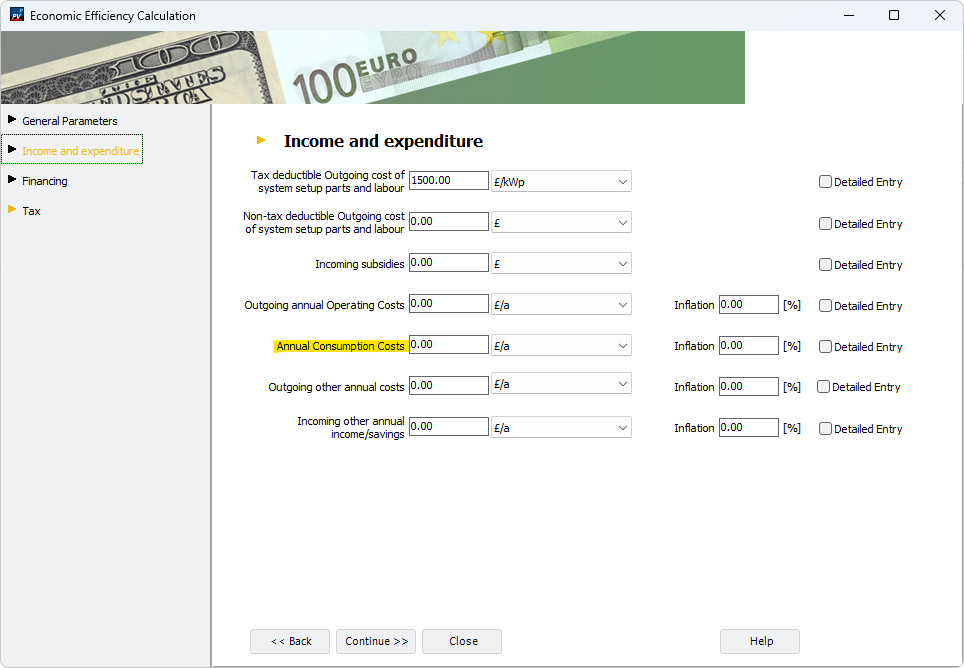
Hi Alain, I guess you are referring to this one here: This is just another item for entering specific cost positions in the economic calculations. It is treated the same way as e.g. "Outgoing annual Operating Costs" and "Outgoing other annual costs". The term originally came from the economics of combined heat and power plants and is not really suitable for pure PV systems. However, if you have a thermal system with an external boiler, you could enter costs that are related to the purchase of fuel, for example. Hope that helps, kind regards, Martin
-
Hi Alin Furcea, the system type that you would require is not available (yet) in PV*SOL. It is very high on our priority list, but I can't give a date of release yet. In the meantime you can add the heat pump as electrical appliance, then you can simulate all in one system as required. Just with the disadvantage that the heat pump is treated like a normal consumer and hence not controllable. Best regards, Martin
-
Hi Ivan Stojkovic, thanks a lot for your question. 17% f deviation really is a a lot, given that the meteo data are identical. There will be differences caused by varying values for the diffuse irradiance, as you already assumed, but this can't be responsible for 17% of deviation. But I can't really guess what causes the deviation as long as I don't see the project files. One point where you could start is to compare the energy balance of PV*SOL and PVsyst, perhaps you can see where the main differences occur. Hope that helps, kind regards, Martin
- 1 reply
-
- 1
-

-
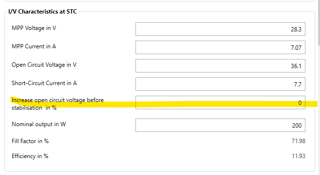
Hi fpWE, the factors can be found in our online help, here: https://help.valentin-software.com/pvsol/en/calculation/pv-modules/module-temperature/ Concerning the light induced degradation, there is this factor here: It is filled in by the manufacturer. If you create your own PV module or copy an existing one, you can change this parameter to your liking. But it is not really important for simulation, as we consider all degradation effects during operation to be summarized in the overall module degradation: https://help.valentin-software.com/pvsol/en/pages/pv-modules/module-degradation/ Kind regards, Martin
-
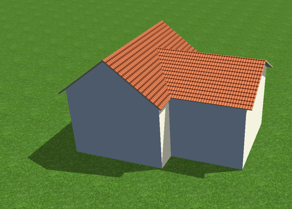
Hallo Haschi0, eine Limitierung in der Testversion gibt es da nicht. Wie war denn dein Vorgehen? Wenn ich einfach zwei Gebäude mit Satteldach ineinander schiebe (Kollision deaktivieren), dann bekomme ich folgendes: Beste Grüße, Martin
-
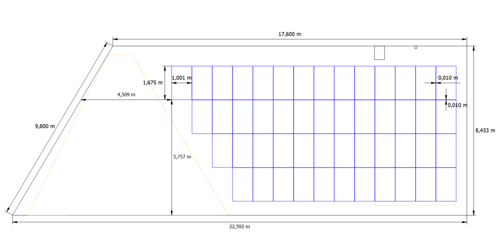
Hallo Solar_ ich habe das eben (nochmal) geprüft, bei mir kommen die Maße korrekt an. Plan aus Beispielprojekt 3D Side Wing: Maße in der dxf (Ausschnitt): Könntest du uns mal das Projekt und die dxf zukommen lassen, bitte? Gerne hier im Forum als private Nachricht, danke. Beste Grüße, Martin
-

Volleinspeisung & Überschusseinspeisung zusammen planen
developer_mh replied to Tempest's topic in PV*SOL
Hallo Norman, wenn man keine Verbraucher hat, kann man nur Volleinspeisung wählen. Mit Verbrauchern kann man wählen zwischen Überschusseinspeisung und Net Metering. Letzteres ist für Deutschland allerdings nicht zutreffend. Volleinspeisung in Kombination mit Überschusseinspeisung in einem Projekt ist derzeit nicht möglich. Die beiden Anlagenteile muss man also in zwei Projekte auftrennen. Beste Grüße, Martin -
Hallo N.Pauly, ja, diese Anlagenart gibt es derzeit nicht in PV*SOL. Dieses Feature steht sehr weit oben bei uns auf der Liste, aber ich kann leider derzeit nichts dazu sagen, wann es kommen wird. Man kann aber zum Beispiel eine Anlage mit Batterie und E-Fahrzeug machen, und dann den elektrischen Bedarf der Wärmepumpe als Lastprofil anlegen. Das ist zwar nicht das gleiche, vor allem weil die Wärmepumpe dann als "normaler" Verbrauch behandelt wird und damit quasi nicht steuerbar ist, aber man bekommt schon mal ein grobes Ergebnis. Beste Grüße, Martin
-
Hallo Tamara Hüser, PV*SOL ist prinzipiell (so gut wie) unbegrenzt in der Leistung, die berechnet werden kann. In der 3D Planung allerdings liegt das Limit für aufgeständerte Module bei 7500, für dachparallele bei 10000. Möchte man 50 MW simulieren, bräuchte man grob 100 000 Module. Da würde ich empfehlen, das Projekt in kleinere Einheiten aufzuteilen. Freiflächenanlagen dieser Größenordnung mit all ihren spezifischen Anforderungen sind aber ehrlich gesagt auch nicht der Hauptanwendungsfall von PV*SOL. Modultische, die dem Terrain folgen, sind z.B. nur sehr schwierig umzusetzen. Beste Grüße, Martin


