


developer_ah
-
Posts
28 -
Joined
-
Last visited
-
Days Won
5
Recent Profile Visitors
4,995 profile views

developer_ah's Achievements
")
Newbie (1/14)
5
Reputation
-
The topics of the webinar: - On-Grid system - with net metering and electric vehicle - MeteoSyn - Load profiles - Photo Plan, Roof view - Polymorphic configuration and power optimizers
-
- 2
-

-
- power optimizers
- polymorphic configuration
- (and 7 more)
-
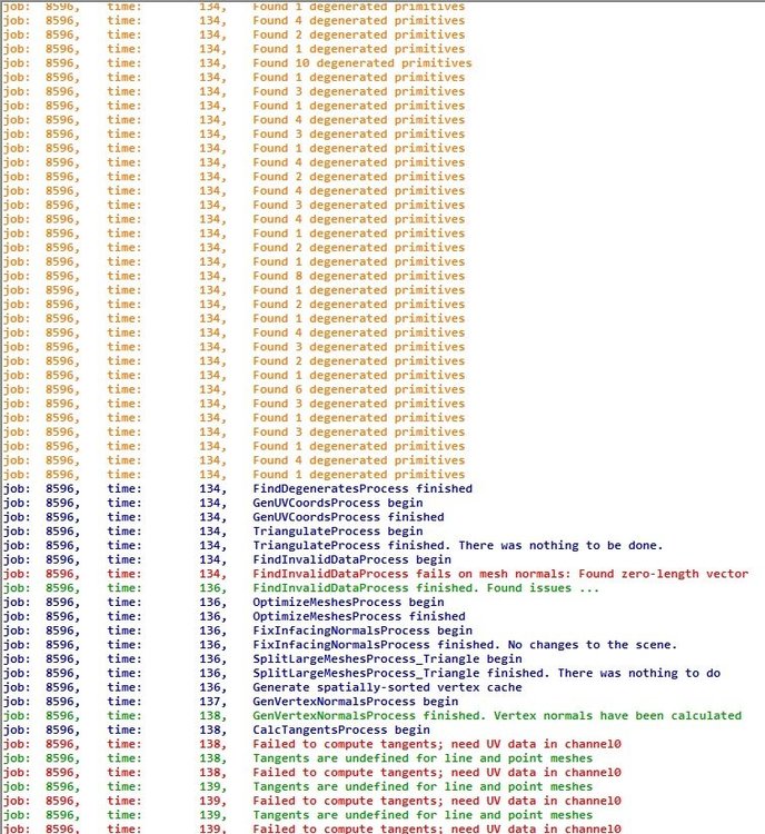
Hallo Alex, ich habe ebenfalls die .3ds-Files heruntergeladen und ausprobiert und ja, keines der Files lässt sich in PV*SOL laden. Um solche Dateien laden zu können, benutzt PV*SOL intern einen Importer, der erst das .3ds-File in ein .obj-File umwandelt. Normalerweise funktioniert das auch. Ich habe gerade geprüft, ob andere .3ds-Dateien noch geladen werden können. Keine Probleme. Also habe ich Open3Mod geöffnet. Das ist ein kostenloses Tool, mit dem man 3D-Dateien anschauen und auch in andere Formate konvertieren kann. Das kannst du gern mal ausprobieren. Dieses Tool nutzt dieselbe Schnittstelle, wie wir, repariert aber noch mehr degenerierte Files, als PV*SOL es kann. Das Tool hat ein Logfile angelegt (Screenshot habe ich beigefügt). Dieses Logfile zeigt jede Menge Unstimmigkeiten bei den Files an. Es ist mir nicht einmal gelungen, es selbst in .obj umzuwandeln. Daher schlage ich vor, du nimmst die Files, die auf der Homepage in anderen Formaten vorliegen und versuchst sie mit Blender oder andere freien Konverter (z.B. Open3Mod) erst einmal in ein komplett fehlerfreies .obj-File umzuwandeln und erst dann in PV*SOL zu laden. Viele Grüße, Chris
-
Extract Google Earth 3D models with Pix4D and PV*SOL
developer_ah replied to Low Carbon Exchange's topic in PV*SOL
You're alluding to a tutorial that one of our partners did. Unfortunately, we cannot present external software programs in the PV*SOL Forum. I can only say that I personally use the c't tool ac'tivAid to make screenshots. In addition, these should be done in the best possible resolution for the monitor and also at least 30 from different angles! -
Extract Google Earth 3D models with Pix4D and PV*SOL premium 2018 http://www.valentin-software.com/services/fw/yt-tut-en/dl-pvsolprem-en [Full Traskript] 1. Create screenshots in Google Earth Pro 2. Photogrammetry with Pix4D 3. Import of the 3D model into PV*SOL premium First, start Google Earth Pro. For this video I chose a free-standing, relatively complex building in England. Here I enter the coordinates of the object. A 3D model is to be extracted from this object. First, I determine the size of an edge of the model. This is later used in PV*SOL to reproduce the scale. To do this I use the ruler function of Google Earth and draw a 3D path to an edge that is well visible. The measured length of the edge is approx. 20m. In the next step I will take about 30 - 40 screenshots of the scene to create a 3D model in Pix4D. In order to achieve an optimal result with photogrammetry, all labels and menus should be hidden first. Now the screenshots can be made. Recommendation: take pictures at 3 different altitudes: - 12 pictures at the height of the ridge or the highest point of the building. - 8 pictures from different angles of the bird's eye view - 12 pictures at a height of 3 meters Make sure - that the target building is always completely visible, - that potential additional shading objects are visible, - and that the pictures are not too twisted. The more images that are created from different perspectives, the better the 3D model created later on will be. In some photogrammetry programs it is useful to take some close-ups as well. Also move the mouse out of the picture before creating the screenshot, so that the mouse cursor is not visible in the picture! After you have made the 30-40 screenshots, start Pix4Desktop. You can currently download this program as a 14-day trial version by creating a customer account on: https://pix4d.com/product/pix4dmapper-photogrammetry-software/ After you have started Pix4Dmapper Pro, you will be taken to the "Home" page of the program. First, create a new project. The "New Project"dialog opens. Here you can select the project folder. Enter the project name here. In the next step the screenshots will be added. Click on "Add Images". Now select all screenshots with "Ctrl-A". The following message can be ignored. Here you can now see an overview of the geodata and the camera model, which were determined from the images. Due to the fact that I made screenshots, not much data is included. The following pages are currently not interesting. Click your way through. On the last page you can see an overview of the level of detail expected for the finished 3D model and how long the creation process will probably take. Select the menu item "3D Models" and then click "Finish". The map view is now displayed. This is not interesting at the moment, because there is no geoinformation in the pictures. The next step is to create the 3D model. Before I click on "Start", let's first look at the options for this. Click "Process", and then click "Process Options". At first, only the settings for "Process" and "Point Cloud and Mesh"are interesting. I leave the general process options unchanged. Make sure that "Keypoints Image Scale" --> "Full" is selected. You can experiment a little later on with the settings for the "Point Cloud" to get an even better result. I leave the settings unchanged. A few things have to be adapted to the mesh options so that the 3D model can be imported correctly into PV*SOL premium later on. I want the textures from the screenshots to be transferred into the 3D model. We set the "Maximum Octree Depth" to 14. The maximum "Texture Size" should be 4096 pixels. The maximum number of triangles has to be limited for the level of detail, because PV*SOL premium currently only accepts 3D models with a maximum of 500,000 points. You can achieve this with the decimation strategy "Sensitive". A model file is automatically generated after photogrammetry is complete. Here you specify that this file is to be created in obj format. Now the 3D model can be created. First, perform step 1 only! This process can take several minutes. I'm fast-forwarding. The result now shows the reproduced positions of the camera and the tie points. The camera positions can be hidden. Unfortunately, the program sometimes has difficulties in determining the correct position of the model from the screenshots. Here you can see a completely unnatural slope which has to be corrected. The "Orientation Constraints" function is used to correct the alignment and inclination of the model. Place the ends of the 3D arrow at a distance you know to be parallel to the height axis. (Here z-axis!!) Step 1 must now be revised. The model has now been corrected. Next, the triangle mesh can be generated. I'm fast-forwarding again. Now the 3D model is already complete and can be viewed. If you want to view the mesh, you must first activate "Triangle Meshes". I just want to view the triangulated mesh and disable the other elements. You can see that the 3D model is already close to the Google original. Now open PV*SOL premium 2018 or a higher version! I am already in the 3D visualization of PV*SOL premium and have started a new project there. Now import the 3D model you created with Pix4D. To do so, click this button. You will find the. obj file, as well as materials and texture in the project folder that Pix4D has created. I simply place the 3D model in the middle of the terrain. As you can see, the 3D model is stored in an unusual coordinate system, which has to be corrected. To do this, double-click on the model and select the "Tilt backward" option. The model has also been well imported into PV*SOL premium. Here already with representation of the shading. Now check the distance measured in Google Earth. To do this, draw a PV area polygon. As you can see, the model is not to scale. It must be corrected (see video). The alignment must also be adjusted! The building can then be covered with PV modules. End of the tutorial. Thank you for watching! The computer program shown is PV*SOL premium, a design software by Valentin Software in the field of photovoltaics / renewable energy. The priorities of this software are design support and yield calculation. The integrated 3D visualization determines the impact of shading on the yield. Another focus is on the cost-effectiveness of photovoltaic systems with and without self-consumption
-
Hello James, could you please contact our support and, if necessary, also send the projects mentioned? I'll look into it then. Thank you very much. hotline@valentin-software.com Many greetings.
-
Hello Stuart, yes, 400MB ist far to much. PV*SOL ist a 32 Bit application. So the maximum size ist 250MB and the maximum number of points is 500.000. But even this can be to much, if you want to do a fast planning. Make you life as easy as possible and reduce the files on a minimum. The greather a model file, the more time PV*SOL need to calculate for ex. the shading, because every single Triangle of the model now can evoke shading. We apoligize the empty message. Its a error. It says that the file ist too big. Many greetings!
-
Hallo, ja, das ist ja schon eine nette Idee, die Sperrabstände in den Default-XMLs zu ändern. Bei den Randabständen ist das nicht so einfach, weil nur die Randabstände, welche geändert wurden, in einer Projekt-XML im Tempordner abgelegt werden. Diese nachträglich zu ändern, macht keinen Sinn, weil die Datei bei jedem neuen Projekt neu angelegt wird. Eine Möglichkeit wäre, sich ein Rumpfprojekt anzulegen mit einem Gebäude, welches überall die gewünschten Randabstände hat. Das gleiche gilt für das Montagesystem für die Modulaufständerung. Einfach anlegen und mit dem Rumpfprojekt abspeichern. Man könnte sich sogar ein paar vorgefertigte Fenster und andere 3D-Objekte auf einem anderen Gebäude anlegen und diese bei der Planung auf das Gebäude kopieren. Das "Als Standard speichern" beim Montagesystem funktioniert derzeit leider nur innerhalb eines Projekts. Die Werte sollten natürlich auch bei "Projekt Neu" zur Verfügung stehen. Wir werden das aufnehmen. Den Standort als "Standard" speichern, funktioniert bei mir. Nach Projekt Neu wird immer der neue Standort angezeigt. Viele Grüße
-
http://www.valentin-software.com/services/fw/yt-tut-de/dl-pvsolprem-de 1. Screenshots anfertigen in Google Earth Pro 2. Photogrammetrie mit Pix4D 3. Import des 3D-Modells in PV*SOL premium Starten Sie zunächst Google Earth Pro. Für dieses Video habe ich ein frei stehendes, relativ komplexes Gebäude in England gewählt. Ich gebe hier nun die Koordinaten des Objekts ein. Von diesem Objekt soll ein 3D-Modell extrahiert werden. Als Erstes ermittle ich die Abmessung einer Kante des Modells. Diese wird später in PV*SOL benötigt, um den Maßstab zu reproduzieren. Hierzu nutze ich die Lineal-Funktion von Google Earth und zeichne einen 3D-Pfad an eine gut sichtbare Kante. Die gemessene Länge der Kante beträgt ca. 20m. Im nächsten Schritt werde ich von der Szene ca. 30 - 40 Screenshots anfertigen, um daraus später in Pix4D ein 3D-Modell zu erstellen. Um bei der Photogrammetrie ein optimales Ergebnis zu erzielen, sollten zunächst alle Beschriftungen und Menüs ausgeblendet werden. Nun können die Screenshots angefertigt werden. Empfehlung: Machen Sie Bilder auf 3 verschiedenen Flughöhen: - 12 Bilder auf Höhe des Firstes bzw. des höchsten Punkts des Gebäudes. - 8 Bilder aus verschieden Winkeln der Vogelperspektive - 12 Bilder auf 3 Metern Höhe Achten Sie darauf, - dass das Zielgebäude immer vollständig zu sehen ist, - dass pot. zusätzliche Abschattungsobjekte zu sehen sind, - und dass die Bilder nicht zu verdreht sind. Je mehr Bilder aus verschiedensten Perspektiven anfertigt werden, desto besser ist später das erstellte 3D-Modell. Bei manchen Photogrammetrie-Programmen ist es sinnvoll, zusätzlich noch einige Nahaufnahmen zu machen. Bewegen Sie auch die Maus vorm Erstellen des Screenshots möglichst aus dem Bild, damit der Mauscursor nicht im Bild zu sehen ist! Wenn Sie die 30-40 Screenshots angefertigt haben, starten Sie anschließend Pix4Ddesktop. Sie können dieses Programm derzeit als 14 Tage-Testversion herunterladen, indem Sie sich auf: https://pix4d.com/product/pix4dmapper-photogrammetry-software/ ein Kundenkonto anlegen. Nachdem Sie Pix4Dmapper Pro gestartet haben, gelangen Sie auf die "Home"-Seite des Programms. Legen Sie als Erstes ein neues Projekt an. Es öffnet sich der Dialog "Neues Projekt". Hier können Sie den Projektordner auswählen. Hier geben Sie den Projektnamen ein. Im nächsten Schritt werden bereits die angefertigten Screenshots hinzugefügt. Klicken Sie auf "Bilder hinzufügen" Wählen Sie nun mit "Strg-A" alle Screenshots aus. Die folgende Meldung kann ignoriert werden. Hier sehen Sie nun einen Überblick über die Geodaten und das Kameramodell, welche aus den Bildern ermittelt wurden. Dadurch, dass ich Screenshots erzeugt habe, sind nicht viele Daten enthalten. Die nächsten Seiten sind derzeit nicht interessant. Klicken Sie sich weiter durch. Auf der letzten Seite sehen Sie im Überblick, welche Detailtiefe beim fertigen 3D-Modell erwartet werden kann und wie lang der Erstellungsprozess wahrscheinlich dauert. Wählen Sie noch den Menüpunkt "3D-Modelle" und klicken Sie anschließend "Finish". Es wird nun die Kartenansicht angezeigt. Diese ist derzeit uninteressant, da keine Geoinformationen in den Bildern enthalten sind. Als nächstes kann bereits das 3D-Modell erzeugt werden. Bevor ich auf Start klicke, schauen wir uns zuerst die Optionen hierfür an. Klicken Sie auf "Prozess" und anschließend auf "Prozessoptionen". Interessant sind zunächst nur die Einstellungen zum "Prozess" und zu "Punktwolke und Mesh". Die generellen Prozessoptionen lasse ich unverändert. Achten Sie darauf, dass bei "Keypoints Image Scale" --> Full gewählt ist. Mit den Einstellungen zur "Punktwolke" können Sie später etwas experimentieren, um ggf. ein noch besseren Ergebnis zu erzielen. Ich belasse die Einstellungen unverändert. An den Meshoptionen müssen ein paar Dinge angepasst werden, damit das 3D-Modell in PV*SOL premium später korrekt importiert werden kann. Ich möchte, dass die Texturen aus den Screenshots in das 3D-Modell übertragen werden. Die maximale Octree Tiefe setzen wir auf 14. Bei der Texturgröße (Textursize) sollten maximal eher 4096 Pixel eingestellt werden. Beim Detailgrad muss die maximale Anzahl Dreiecke eingeschränkt werden, da PV*SOL premium derzeit nur 3D-Modelle mit maximal 500.000 Eckpunkten akzeptiert. Das erreichen Sie mit der Dezimierungsstrategie "Sensitive". Nach Abschluss der Photogrammetrie wird automatisch eine Modell-Datei erzeugt. Hier legen sie fest, dass diese Datei im Format .obj angelegt wird. Nun kann das 3D-Modell erzeugt werden. Führen Sie zunächst nur Schritt 1 aus! Dieser Vorgang kann mehrere Minuten dauern. Ich spule vor. Sie sehen nun im Ergebnis die reproduzierten Positionen der Kamera und die Tie Points. Die Kamera-Positionen lassen sich ausblenden. Das Programm hat leider manchmal Schwierigkeiten, die korrekte Lage des Models aus den Screenshots zu ermitteln. Hier sieht man ein völlig unnatürliches Gefälle, welches korrigiert werden muss. Zur Korrektur der Ausrichtung und Neigung des Modells gibt es die Funktion "Orientation Constraints". Setzen Sie die Enden des 3D-Pfeils an eine Strecke, von der Sie wissen, dass sie parallel zur Höhenachse verläuft. (Hier z-Achse!!) Schritt 1 muss nun überarbeitet werden. Das Modell ist nun korrigiert worden. Als Nächstes kann das Dreiecks-Mesh generiert werden. ich spule wieder etwas vor. Nun ist das 3D-Modell bereits komplett und kann betrachtet werden. Wenn Sie das Mesh betrachten möchten, müssen Sie zunächst "Triangle Meshes" aktivieren. Ich möchte nur das triangulierte Mesh betrachten und deaktiviere die anderen Elemente. Sie sehen, dass das 3D-Modell schon nahe an das Google Original heranreicht. Öffnen Sie nun PV*SOL premium 2018 oder eine höherer Version! Ich befinde mich bereits in der 3D-Visualisierung von PV*SOL premium und habe dort ein neues Projekt begonnen. Importieren Sie nun das 3D-Modell, welches Sie mit Pix4D erstellt haben. Klicken Sie hierzu diesen Button. Sie finden die .obj - Datei, sowie Materialien und Textur im Projektordner, den Pix4D angelegt hat. Ich platziere das 3D-Modell einfach in die Mitte des Terrains. Wie Sie sehen, ist das 3D-Modell in einem unüblichen Koordinatensystem abgespeichert, welches korrigiert werden muss. Machen Sie dazu einen Doppelklick auf das Modell und wählen Sie die Option "Tilt backward". (Nach hinten neigen) Auch in PV*SOL premium ist das Modell gut importiert worden. Hier bereits mit Darstellung des Schattens. Überprüfen Sie nun noch die Länge der in Google Earth ausgemessenen Strecke. Zeichnen Sie dazu ein Belegungsflächen-Polygon ein. Sie sehen, dass das Modell nicht maßstabsgerecht ist. Es muss korrigiert werden (Siehe Video). Außerdem muss die Ausrichtung angepasst werden! Anschließend kann das Gebäude mit PV-Modulen belegt werden. Ende des Tutorials. Vielen Dank fürs Zuschauen! Bei dem zuletzt vorgestellten Programm handelt es sich um PV*SOL premium, eine Planungssoftware der Firma Valentin Software aus dem Bereich Photovoltaik (Regenerative Energien). Schwerpunkte dieser Software sind die Planungsunterstützung und Ertragsprognose. Mit der integrierten 3D-Visualisierung wird der Einfluss der Abschattung auf den Ertrag berücksichtigt. Ein weiterer Schwerpunkt ist die Wirtschaftlichkeit von Photovoltaikanlagen mit und ohne Eigenverbrauch.
-
Hello, case 2 is clearly an error that has already been reported. If the building contains a completely closed attic, the shading simulation has difficulty in correctly determining the shading. You can see this by the fact that some shading values of over 60% are of course much too high. We apologize for that and we're working on it. In the meantime, please create the attics in sketchup as several broken walls if you have created the sketchup file yourself. This should fix the problem. In the first case, the model is constructed in such a way that the error not occurs. Please be aware that the model geometries may have been stored in two different ways in the file. In one case, for example, only triangle faces are stored in the file; in the other case, for example, complete fans are stored. In addition, optimization may have become active when exporting to a certain format, so that different files can be created for the same model. Normally this does not affect the results of the shadow calculation! Many greetings!
-
Hello Martin, thank you very much for what you found out! I have received the files. I will try to reproduce that issue. Many greetings!
-
http://www.valentin-software.com/services/fw/yt-val-en/dl-pvsolprem-en [Transkript] In this tutorial you will learn how to use photo matching to model your building with SketchUp and use it in PV*SOL premium. "You will need: - Two Pictures of the building you like to model - SketchUp Make or Pro - PV*SOL premium 2018" The pictures should be taken at a 45° angle from two opposite corners. Next we create a folder structure containing our project data. Create a new folder, rename it and create three subfolders "Models", "Images" and "Exports". Drop the pictures into the "Images" folder. Start SketchUp. Activate the used tools by right click the toolbar and select the tools as needed. Open the drop down menu "Camera" and select "Match New Photo...". Navigate to your "Images" folder and select an image. The yellow square is the origin of the coordinates. The red line is the x-axis, green the y-axis and blue the z-axis. Pull the yellow square onto a corner of the roof. The corner should be visible from both pictures. Now drag the y-axes (green dashed line) on two parallel edges of the building and align them with the green squares at the end of the lines. Do the same with the x-axis. The x- and y-edges of the house must be offset by 90° to the y axis. To check the alignment, you can drag the origin to another corner of the house. The z-axis should coincide with a vertical edge of the house. For adjusting you can use the x- and y-axis handles. Check the alignment with other edges of the house. When you hover with your mouse over the z axis, the cursor changes into two little arrows. Click with the left mouse button and change the scale by moving the mouse. To complete the photo match click with the right mouse button and select "done". Select the Rectangular Tool and draw the base surface of the front roof from the coordinate origin. Select the Tape Measure Tool, move the mouse over the z-axis until a red square appears. Then click with the left mouse button and move the guide line to the center point (blue circle) of the edge. Select the line tool and draw the front edge of the roof. Make sure that the end point of the line is on the guide line. If you press the middle mouse button and hold it down, you can rotate the view by moving the mouse. Draw the remaining edges of the roof. If you click on the blue tab, the scene changes back to the photo match view. Left click three times to select the whole model. Then click with the right mouse button and select "Make Group". If there is no volume, there is either an open area, a single line or an area within the body. Check if the object has a volume. If there is no volume, there is either an open area, a single line or an area within the body. Select the Rectangular Tool and draw the base of the remaining roof. With activated Select Tool mark the edge and drag it with the Move Tool. Draw a vertical guide line through the middle of the edge. It's time to match the second picture. Repeat the steps from the first photo match. The coordinate origin is located on the same roof corner and the axes must have the same alignment. Adjust the house edge with the move tool. Rematch the first picture by right click on the tab and select "Edit Matched Photo". Adjust the x and y-axis a little bit so that the rear edge of the roof matches the picture. When ready, right click and select "Done". Using the Tape Measure Tool, click on the slanted roof edge and type in 0. The guide line should be on the edge. Draw a vertical guide line through the center of the page. Select the Line Tool and draw the side of the roof from the intersection point of the guide lines. Remove the guide lines by clicking on edit in the menu bar and select "Delete Guides". Left click three times to select the whole model. Then click with the right mouse button and select "Make Group". Check if the object has a volume. If there is no volume, there is either an open area, a single line or an area within the body. Now we model the chimneys and roof windows. Select the Line Tool and draw on the surface of the roof. Move the cursor over the top edge of the roof and look for the pink 90° offset reference line. Extrude the surface with the Push/Pull Tool by about 1 cm. To do this, select the tool, then click on the area and type in 0.01. With the Line Tool you can model the chimney. When drawing the lines, make sure that you snap into the axes (x, y, z). The drawn line is colored according to the reference axes. The color of the surfaces is darker than the remaining surfaces. This is because the normal of the flats are twisted. The dark areas should be inside the object. To invert, right-click on the surface and select "Reverse Faces". In order for an object to become a solid body, there must be no surfaces within the object. The internal surface of the chimney must be removed. To do this, we select the area and delete it with the Delete key. Left click three times to select the whole model. Then click with the right mouse button and select "Make Group". Repeat the steps for modelling the remaining roof details. This time we don't create a group, but choose "Make Component...". The difference between a group and a component is the linking of copies of these objects. This means that changes to a copy of a component are automatically applied to all other copies of that component. There are three identical roof windows. We only model one window and make copies of the component. If we want to change the roof window in retrospect, we only have to change one copy. To make a copy of the window, select the move tool and press the ctrl on the keyboard. A small plus on the cursor indicates that we are in copy mode. Then we go to a corner of the window and click with the left mouse button. Now we drag the copy to the next window position. Next we model the roof frame. First of all, we draw the shape of the frame with the Line Tool. Then we draw the roof shape. For a better view we move the objects to individual layers. To do this, we click on the plus sign in the layer section of the side menu and then we name our new layer. Afterwards we mark the objects and change the layer in the section "Entity Info" in the side menu to the newly created layer and we uncheck the Visible option. Repeat the steps for the other models. Mark the surface. Then select the Follow Me Tool and click on the shape of the roof frame. The color of the surfaces is darker than the remaining surfaces. This is because the normal of the surfaces are twisted. The dark areas should be inside the object. To invert, right-click on one surface and select "Reverse Faces". Then right-click again and choose "Orient Faces". Delete the surface. Triple click on the model and "make group". Check if a volume is displayed. Move the objects to individual layers. To do this, we click on the plus sign in the layer section of the side menu and then we name our new layer. Afterwards we mark the objects and change the layer in the section "Entity Info" in the side menu to the newly created layer and we uncheck the Visible option. To model the ground floor, we need reference lines. To do this, we select the Tape Measure Tool and move a reference to the z-axis (blue) to the house edge. It is important that the reference line is "drawn" on the roof, otherwise it hangs somewhere in the 3d-room and has no relation to the house. Then we use the Line Tool to draw an edge from the reference line along the y-axis. The Line Tool automatically snaps into the x-axis. Then we move the edge with the move tool along the reference line until it matches the house edge. Repeat the steps for the remaining edges. Delete protruding edges with the Erase Tool. Then use the Pull/Push Tool to extrude the ground surface. Save your project in the models folder. Next we assign materials to the objects. To do this, we open the material menu and select the desired materials. For simplicity's sake, I use the materials that are already in the model. To apply the materials, we simply click on the desired object. To export the model we select in the file menu export > 3d model. We select "*. dae" file and click on options. Select "Triangulate All Faces" and "Export Texture Maps". Click on "Export". "In PV*SOL premium select the import option, load the exported model and drag it into the simulation environment. The scale of the model may need to be adjusted." Your model is ready for simulation. Thank you for watching. As texture we use the background images from the Photo Match perspectives. Activate the Photo Match view by clicking on the corresponding tab. Double-click on the "Roof" object to activate it. Then select the roof surface. Then right-click and choose "Project Photo". Repeat the steps for all visible surfaces of your object. Do the same with the other objects of the house. If the question is asked: "Trim partially visible faces?" it is important to answer with "no". Repeat the steps for all objects with both views.
-
Could not Import .obj from pix4d exported mesh
developer_ah replied to Francis Bajet's topic in PV*SOL
Hello Francis, I am quite sure that your file has more vertices than the 500.000 which is the maximum in PV*SOL premium. There is a translation error in the message box. It currently shows no text. Normally it says that the file ist to big! You have to reduce the amount of points in Pix4D. Try to remain below 200.000 points. The bigger the file the more is the imperformance during the shading calculation etc. For the import of the other file formats PV*SOL uses the Assimp libary. The error shows you that the Assimp Wrapper was not able to import the file. Maybe try the tool "Open3Mod" to load the files, reduce the points an convert the files into .obj. Many greetings! -
Hallo Martin, please send all project files and the complete model in a zip to our support team (hotline@valentin-software.com). We will try to fix that problem. Make sure that you have the textures too! If you can reproduce the issue another time. I would be very grateful if you could write down the steps and send them as well, so that we can fix the possible error. Many greetings!
-
New PV*Sol 2018 is excellent, some small problems.
developer_ah replied to jamesbm's topic in PV*SOL
Hello James, first of all, we are very happy that they like this feature. Answer 1) Of course you are absolutely right! Since the Boundingboxes of imported 3D-models are rather rough, it can be difficult to push the models together. I have already added the feature for Release 2. Answer 2) Could you please send the project file to hotline@valentin-software.com, then I can have a look at it. Many greetings -
This usually has something to do with your system settings or graphics card drivers.In this case, a DirectX 9.0c feature is not supported, which is needed to display this 3D text.You could try to update your graphics card drivers or choose another graphics card. Please contact our support if the problem persists.
