-
Posts
1,316 -
Joined
-
Last visited
-
Days Won
83
Everything posted by developer_fw
-
Hi Miroslav S, thank you for reporting this! I forwarded your request to our database team. Best regards, Frederik
-

SMA STP Smart Energy / Falsche Angaben zur Kopplung
developer_fw replied to MN_SOL's topic in PV*SOL
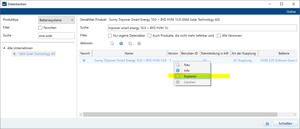
Hallo MN_SOL, das ist in der Tat falsch eingetragen, vielen Dank für die Anmerkung! Wir ändern das in unserer Onlinedatenbank. Bis zum nächsten Update der Onlinedatenbank kann der Datenbankeintrag in PV*SOL kopiert und anschließend im kopierten Eintrag die Art der Kopplung geändert werden: Beste Grüße, Frederik -
Hello Bhd, we are aware of problems related to high DPI settings. Might you be so kind and try the steps described in this thread? (The problem in the thread is a scaling issue, but hopefully originates also from the high DPI settings) I hope this helps. If your problems remain, please feel free to ask again! Best regards, Frederik
-
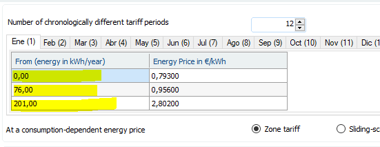
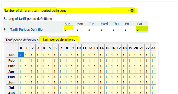
Hello Heymo, what do you mean by Tariff periods in the first column? It is possible to set several energy prices depending on energy bands. The marked tariff periods P1...P5 ...could be translated into the energy bands that are configurable with our Net-Metering Tariffs: Regarding to the period P6 in your table: Generally the separation into weekends/holidays | Monday-Fridays is possible via the definition of separate period definitions here BUT unfortunately the number of different tariff periods is currently limited to 12 for the months. So your problem could not be mapped -.- We can try to get rid of the limitation of different tariff periods. I'll check if this opens new challenges within our code. Best regards, Frederik
-

Link different arrays to different energy usages (mpans)?
developer_fw replied to PV designer's topic in PV*SOL
Hi PV designer, this is already on our list of feature requests, but not yet implemented. Best regards, Frederik -
Hallo Tocho, ja, das ist unter Optionen > Programmoptionen > Erweitert einstellbar. Weiteres auch in unserer Onlinehilfe: https://help.valentin-software.com/pvsol/2022/de/optionen/#erweitert Viele Einstellungen werden unter C:\Users\<username>\Documents\Valentin EnergieSoftware\PVSOL premium 2022 in der Datei PVSOL.ini gespeichert. Eigens angelegte Datensätze können durch Austauschen der Benutzer-IDs geteilt werden: https://help.valentin-software.com/pvsol/2022/de/datenbanken/#benutzer-ids Ich hoffe das hilft weiter. Beste Grüße, Frederik
-
Hi Carlos33, Could you please send me the project file via private message here in the forum so I can have a look? A PR greater than 1 is indeed impossible, so probably you found a bug. Thanks in advance and best regards, Frederik
-
Hallo Sebowsky, könnten Sie noch ein paar weitere Informationen bereit stellen? Gerne auch per persönlicher Nachricht hier im Forum. Zum Beispiel: Versionsnummer von PV*SOL Log-Dateien (Verzeichnis aufrufbar aus PV*SOL mit CTRL+SHIFT+L) PVSOLpremium.log Wow6432.log Eine Projektdatei, bei der das Programm unbedienbar wird Vielen Dank im Voraus, Frederik
-
Hi M Carba, welcome to the forum and sorry for the belated answer! The greatest impact on the simulation results is caused by the incoming climate data. I do want to refer you to the following answer in a previous thread: Best regards, Frederik
-
Hi Automic, welcome to the forum! Yes, no undo so far. I know this will be no satisfactory answer, but please refer to this thread where I tried to explain our current situation: Best regards, Frederik
-
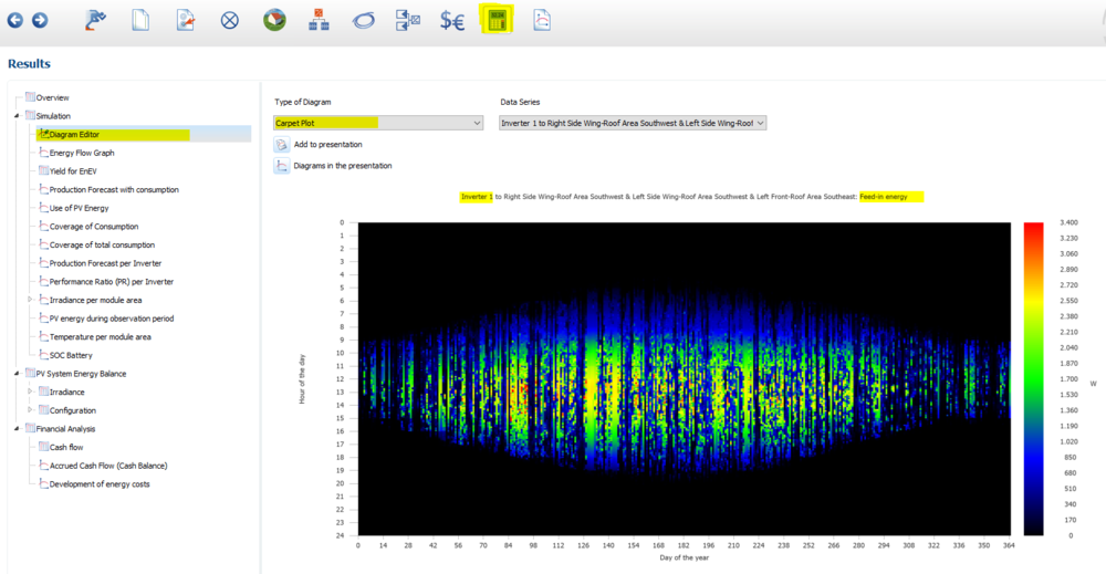
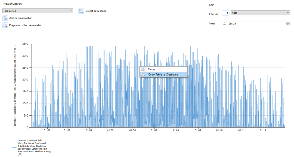
Hi Voltaicsystem, definitely! After the simulation has been completed, detailed results can be inspected with the Diagram Editor. To get an overview over a whole year for specific result parameters, Carpet Plots are highly recommended: Within the Time series graph, data can be copied via a right mouse click: Please also refer to our online help: https://help.valentin-software.com/pvsol/2022/en/pages/results/diagram-editor/#carpet-plot I hope this helps! Best regards, Frederik
- 4 replies
-
- results
- diagram editor
-
(and 1 more)
Tagged with:
-
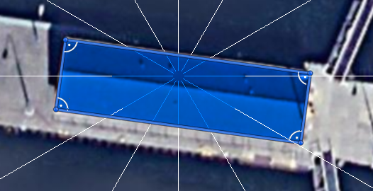
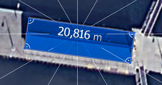
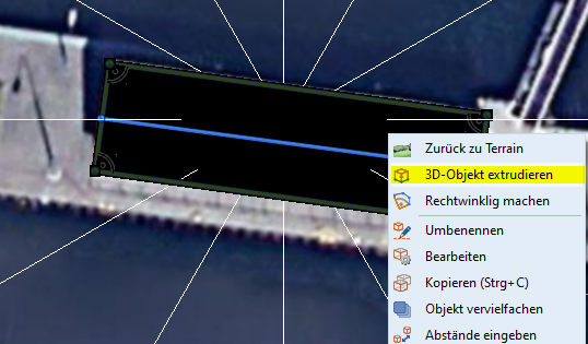
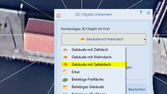
Hallo Francesco, auch wenn die Antwort sehr verspätet ist, hier nochmal die Vorgehensweise; vor allem für zukünftige Anfragen. Nach dem Einzeichnen eines Polygons: Ist entlang des Firstes ein weiteres Polygon als Linie einzuzeichnen: Anschließend mit der rechten Maustaste über das Kontextmenü 3D-Objekt extrudieren aufrufen: Dort steht Gebäude mit Satteldach zur Auswahl: Ich hoffe das hilft weiter. Beste Grüße, Frederik
-
Hallo Lukas615, interessant! Ich habe versucht, diese Darstellung der Attika nachzustellen, aber konnte es bisher in verschiedenen Ausführungen nicht reproduzieren. Wie genau war Deine Vorgehensweise? Welche Grundmaße hat das Gebäude ungefähr? Viele Grüße, Frederik
-
Hallo Lukas615, Deine Recherchen sind korrekt; es soll automatisch erkannt werden, ob es sich um Halbzellenmodule handelt. Leider funktioniert das nicht immer, weshalb schon länger auf der Liste steht, diese Info an 3D weiter zu reichen. Ich stoße das nochmal bei unserem 3D-Entwickler an. Beste Grüße, Frederik
- 2 replies
-
- 3d
- halbzellenmodule
-
(and 1 more)
Tagged with:
-

Cable plan - Exporting multiple module areas
developer_fw replied to Raquel Ribeiro's topic in PV*SOL
Hi Raquel Ribeiro, at the moment, there is no such option in PV*SOL unfortunately. I will forward your feature request to the responsible developer. Best regards, Frederik -
Hallo Awvogel, das ist grundsätzlich möglich. Es können sich in Abhängigkeit vom verwendeten Dateisystem Probleme beim Speichern ergeben (viele kennen das von Dropbox), wenn mehrere Nutzer:innen gleichzeitig schreiben. Viele Grüße, Frederik
-
Hi redpaks, are you able to use PV*SOL for 2 minutes to deregister it following the steps listed in our online help? https://help.valentin-software.com/pvsol/2022/en/start/registration/#license-terms This way you could use the same license. Best regards, Frederik
-
Hi Nola, within PV*SOL there is no such possibility unfortunately. After exporting the diagram as .svg you could rearrange it suiting your needs. One recommended program is https://inkscape.org/ We know there is a learning curve for Inkscape but there are only basic steps needed in this case. Best regards, Frederik
-
Hi Awvogel, zur Zeit bietet unser Vertrieb kein Lizenzmodell an, das solch eine Netzwerknutzung erlaubt. Diese ist auf Einzelmaschinen beschränkt. Beste Grüße, Frederik
-
Hi Venkatesh, thank you for sending the model to me. The automatic recognition of possible mounting surfaces has always been in beta only and never matured to more than an experimental method. In most cases you have to draw those mounting surfaces by yourself. Your model was constructed via photogrammetry or from LIDAR data, which has improved greatly in recent years. One problem is: Instead of having to deal with one flat surface as a roof e.g. from a SketchUp drawing those models come with uneven surfaces due to the fact that the process for creating those models does not receive any information about the building. I would recommend: Free your model from material like the grounds, which are not needed for the shading analysis. Replace uneven surfaces with single surfaces where possible. I hope this helps. If you have further questions, feel free to ask! Best regards, Frederik
- 1 reply
-
- 1
-

-
Hi Esteban, SOC max of 13% sounds odd. Might you send the project file to me via private message here in the forum so I can have a look? Thanks in advance and best regards, Frederik
-
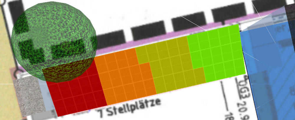
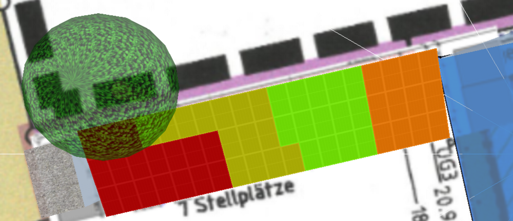
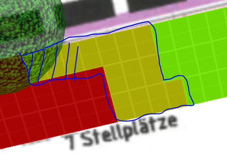
Hallo N_G, ich hatte mich in der Schnelle verlesen und dachte die Verschaltungen der Projekte sind identisch, weshalb auch Deine Fragestellung berechtigt wäre. Die Verschaltung hat in der Tat einen großen Einfluss und sie ist in den beiden Projektdateien unterschiedlich. In der Kaco-Datei sehen die verschalteten Strings folgendermaßen aus: In der RCT-Datei sind die Strings wie folgt angeordnet: Die höheren Verschattungsverluste im RCT Projekt werden durch den gelben Strang verursacht. Die Module auf der linken Seite sorgen für höhere Verluste im gesamten Strang, also alles korrekt. Ich hoffe, das hilft weiter! Beste Grüße, Frederik
-
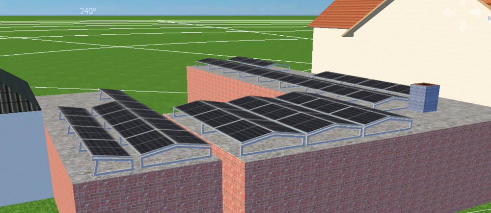
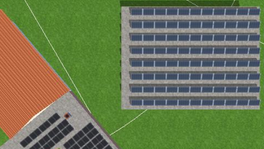
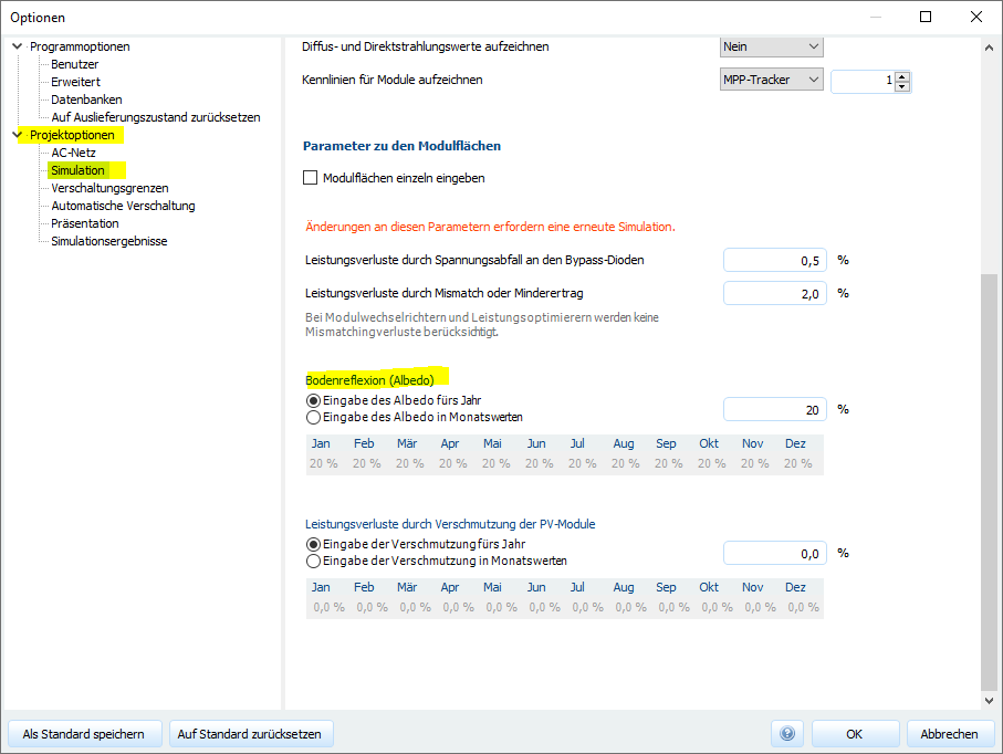
Hallo LR2204, Die gewählte Aufständerung ist eine Ost-West-Aufständerung mit einem flachen Aufstellwinkel von 10°. Auch bei hohen Albedowerten sind die Bifazialitätsgewinne nicht sehr hoch, deshalb werden diese nicht berücksichtigt zugunsten einer schnelleren Simulation. Ich sehe noch nach, unter welchen Bedingungen dies statt findet. Ich habe daneben ein Flachdach mit Südaufständerung und bifazialen Modulen erstellt: In diesem Fall sind auch bifaziale Gewinne in der Bilanz zu finden: Die Bodenreflexion kann unter Projektoptionen > Simulation > Bodenreflexion eingegeben werden. Eingezeichnete Gebäude können nachträglich leider nicht miteinander verbunden werden. Im Falle von komplexeren Gebäuden -- was schnell der Fall ist -- lohnt sich eine Erstellung der Gebäudestrukturen mit einem 3D-Programm, zum Beispiel https://www.blender.org/ oder für einen schnellen Entwurf SketchUp. Ich hoffe, das hilft erstmal weiter. Bei weiteren Fragen gerne weiter fragen! Beste Grüße, Frederik
-
Hi MN_SOL, wir haben diese Anlagenarten bereits auf unserer Featureliste. Derzeit ist diese Art der Simulation noch nicht möglich. Viele Grüße, Frederik
-
Ja, habe ich erhalten und sehe sie mir jetzt an. Viele Grüße, Frederik


