
Frido
Members-
Posts
54 -
Joined
-
Last visited
-
Days Won
7
Everything posted by Frido
-
Hello everyone, just wanted to meantion that I still expirience this bug from time to time in 2021 R4. See screenshot attached, this is from a project with one Moudle Area only. Best Regards, Frido
- 14 replies
-
- workaround
- bug
-
(and 1 more)
Tagged with:
-
Hi Frederik, sorry if I have not communicated this clearly: I am not trying to import climate data. I am trying to generate climate data using the MeteoSyn. So there is no file importing going on on my side. Cheers, Frido
-
Hi Frederik, & thanks for getting back to me! Just to make sure I unterstood correctly: This means that the result found in the "per Module Area" section is the "correct" one? Or is non of them trustworthy at the moment? Cheers, Frido
-
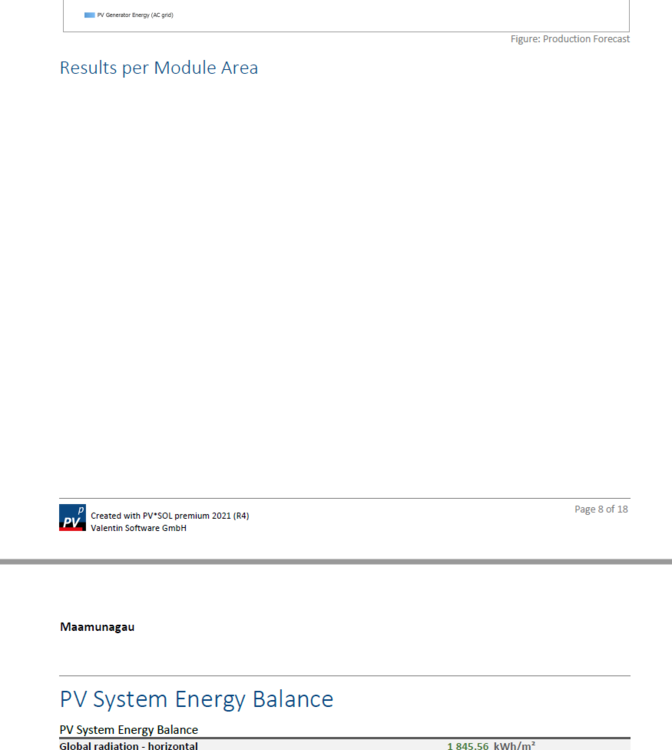
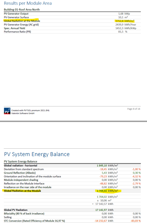
Hello! I have created multiple files at different locations, all of which have one Module Area only. However, the results for the “Global Radiation at the Module” are different ones in the “Result per Module Area” section and in the “PV System Energy Balance”. Shouldn’t they be the same when there is only one Module Area? Can someone please explain the difference? FYI, the idea behind doing this is to compare the simulated irradiation vs. our own irradiation data. Cheers, Frido
-
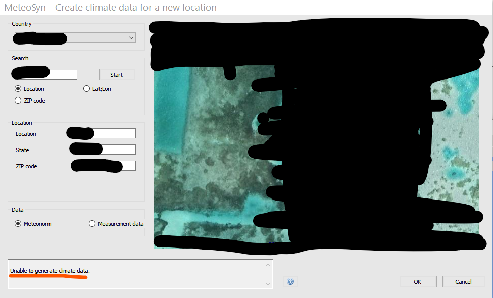
Hi Frederik, thanks for the quick reply. I'd be happy to share the file with you, but unfortunately there is no such file in this directory. See screenshot attached. As a work around, I have used climate data that I have created earlier from a place really close. It is absolutely fine results wise, but it would be nice for the client to see that we used their exact location. And also, I would like to know what to do should this problem occur with a different location (where I do not have existing climate data from a site close by already) in the future. Let me know if there is anything else I can do to assist troubleshooting. Cheers, Frido
-
Hello! I have created climate data for new locations many times in the past, always without any issue at all. But today I got the error text "Unable to generate climate data." multiple times for some locations, some others work. Any idea why that could be? Any workarounds? Cheers, Frido
-
It would be nice to have the "Yield Reduction due to Shading" result not only with the results of the total system, but also with the results per module area.
-
Ah, thanks. I am sorry, for some reason I haven't seen that, even though I was looking for it. Thanks!
-
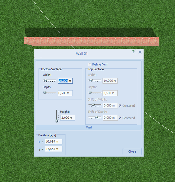
Thanks for the reply! I am afraid I do not know what option "rotatable wall" you are talking about. I only have the option to place a "simple wall", when in Obejct View. However, I have found out the following: Not being able to rotate a wall only happens when it is placed inside an "Open Area" (wall B in picture). When you place it outside (wall A), everything works as expected. I guess this behaviour is a bug. Best, Frido
-
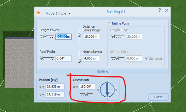
Hello everyone, I am like 99% certain that there always was the option to rotate / orient a wall by changing its azimuth angle, just like with buildings. But now the option seems to be gone? Am I wrong? Any help? Running premium 2020 R9.92 Thanks, Frido
-
Thanks for the workaround Martin! Unfortunately, the workaround came too late for us, but I still want to share how we managed to still get the results needed: We split the finished project (35 Module Areas total) up into two files. Then deleted ~50% of the Module Areas in the one file, and the other 50% in the other file. This means we now have the project split up in multiple files, but at least we got the results we needed after putting all the time into making the PVSOL model. I’d also like to mention that about two weeks ago we were in contact with the hotline via phone and email beacuse we had the same problem again. However they did not provide a fix for the problem. But now you did in the forum, and we only found out about it more or less by accident. Somewhat frustrating. Anyhow, thanks again and sorry for my grumpiness, Frido
- 14 replies
-
- workaround
- bug
-
(and 1 more)
Tagged with:
-
I had the same problem, and this helped. Thanks!
-
When clicking on a Module Array in the list on the left-hand side of the screen, it automatically activates and therefore “jumps” to the selected array. This is unlike the buildings, which just get highlighted when clicking on them. I much prefer the later behaviour and would appreciate if it were the same for the Module Arrays. It would make locating & renaming them much faster & easier.
-
A option to adjust the default values (e.g. Edge Distance) would be nice.
-
Hi Muhammad, Is the fact that it does not have any walls that important to you? For 95% of our projects, the only important thing is that the roof area is depicted correctly. So if I had to the depict the gas station seen in the picture I’d just go ahead with a flat roof building. I have found that it is much faster to do this way, & less prone to errors compared to using a 3D model. I try to avoid using 3D models whenever possible, as they have often caused issues. Regards, Frido
-
When copying a module, and checking the "Make multiple copies" box, the Clipboard still disappears when you decide to "Integrate to Array", instead of staying on the screen (as it does when not checking the multiple copies box) so you can make multiple copies. It is a small thing, but does not seem intentional and would be nice if it was fixed.
-
I have had this a few times, even within the same project. Usually restarting PVSOL does the trick for me. Sometimes, however, multiple tries & a restart of my PC were necessary.
-
I have tried a lot of things (file types) when importing models from DroneDeploy. Usually, the texture is as washed out for me as it is for you. I have managed to import models with vibrant textures in the past (don’t ask me how, it was luck more than anything). However, once I saved and reopened the 3D Visualization, the texture is either washed out again or (parts of it are) missing completely. Unfortunately I have also found that importing such models increases your chance of crashing PVSOL. Therefore, I do not bother anymore, and would not recommend putting time into this.
-
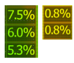
For us, a fixed (or at least globally adjustable) colour scale for the shade frequency analysis would be very useful. So that e.g. 5% of shading has always the same colour for every roof in every project. As it is right now, 5% or even 10% of module shading might appear as a vibrant green, just because a part of the roof (maybe even with no modules) might be shaded very strongly. Not ideal at all. This, along with an option to export these pictures with one press of a button would be very useful to our workflow. As of right now we have to screengrab each and every roof. Edit: exmple picture added.
-
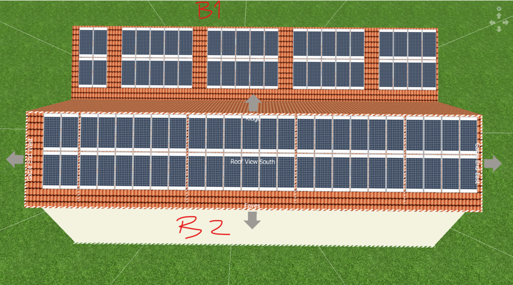
Dear Martin, thanks for your reply. I am happy to hear that you are working on it! I gave it a try jus now, but unfortunately it doesn’t really do the trick. Here is why (please refer to screenshot below): First of, I assure you that the barred areas are the same on both buildings. I just copied the building in the background (B1) as seen on the picture and deleted the modules in order to generate the building in the foreground (B2) B1 was done with the Cover-Tool. As you can see, it just leaves one line of modules blank, and does not start with the next module right after the barred area. So I am afraid this is no good for what I’d like to achieve. B2 is what I’d like the outcome to look like. It was done using the Fill-In-Tool, for each section at a time. Unfortunately, this is a pain for many other reasons. First of all, it is not feasible for large projects. Secondly, this are now 5 separate module arrays. As far is I know, it is not possible to combine them (Please let me know if that’s true or not! imo, it should definitely be possible.). The third point is something that has annoyed me many times before, not just related to this particular case, and this would be something I’d love to be fixed: I have spaced the barred areas in a way that the space in between will fit the exact amount of modules with their respective gaps in between them. This now means, that if I want to use the Fill-In-Tool its practically impossible to place the 12 (6x2) modules in one go, because you’d have o be pixel perfect with your mouse and the area you want modules to be placed in. It would be SUPER helpful, if it was possible to “start” and “end” the rectangle when creating the “Fill-In-Area” in (or even outside of) a barred area! This way, one could assure that 100% of the area one would like to cover is contained within the rectangle one creates when using the Fill-in-Tool. As it is right now I have to create a 5x2 Array, then push it up against one corner, and then copy and paste a 1x2 array (again almost pixel perfect, so I have to zoom in a lot) and integrate it to the existing 5x2 in order to get my 6x2. I hope you get what I mean with my third point. As mentioned, this has caused frustration many times before, and I’d love to see a fix for that! Anyways, thanks for your help and I’d love to hear your thoughts. The thermal gap thing is not hugely important to me right now, but it would definitely be nice to have. Best, Frido
-
Hello everyone, What is the best / easiest way to include Thermal Gaps in a PV*SOL layout? I have not found a convenient way to do this yet. Ideally, this is what I’d like to have: After X (amount) of modules I’d like to have Y (distance) of space before the next module in this row is placed. Where I tell PV*SOL what my X and Y values are. Similar to the module distances settings that you get before placing the modules. Is there such a option? Or is there a easy way to do it? Also, it’d be great if the modules stayed as one array Best, Frido
-
Hallo Martin, gerne sende ich euch die entsprechenden Dateien. Viele Grüße, Frido
-
I have had the same problem on large projects. Sometimes pink, sometimes yellow, sometimes other colores, though I do not recall each colore.
-
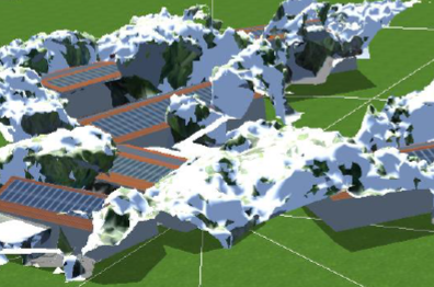
Ich habe in letzter Zeit sehr viel Probleme (importierten) 3D Modellen in PV*SOL Premium 2020 R4. Ich habe das Problem, dass – wenn ich speichere, die 3D Umgebung verlasse und wieder hineingehe – sind viele Modulflächen verschoben, schweben in der Luft etc. Siehe Screenshot. Hier mein Vorgehen: -3D Modell importiert (.obj) -Modell entsprechend gekippt und ausgerichtet -Flächen automatisch erkennen lassen -Alle (acht) Dachflächen belegt. (das hat sehr gut und ohne Probleme funktioniert) -Gespeichert -3D Umgebung verlassen -3D Umgebung wieder betreten -> Modulflächen verschoben (siehe screenshot) Meine Frage: Ist das ein bekannter Fehler? Wie kann man ihn verhindern? Ist ein anderer Dateityp (nicht .obj) besser? Kann das an der automatischen Erkennung der Flächen liegen (hab das Feature hier zum ersten mal benützt)? Ist das manuelle zeichnen der Dach-/Modulflächen weniger Fehler anfällig? Zusätzlich als sehr störend aufgefallen ist mir folgendes: Wenn ich die .obj Datei lade, hat das ganze Modelle eine angenehme grau Farbe / Textur. Giebel / Traufe / Kanten etc. sehr gut erkennbar. Nach dem verlassen und wieder betreten der 3D Umgebung ist das Modell ganz weiß. Dies schadet der Erkennbarkeit des Modells massiv! Kannten sind quasi nicht mehr erkennbar. Mein Workaround ist, dass ich die Sonne sehr tief setze und entsprechend hilfreiche Schattenwürfe bekomme. Das ist aber alles andere als ideal. Beste Grüße.

