developer_mo
-
Posts
261 -
Joined
-
Last visited
-
Days Won
12
Everything posted by developer_mo
-

Batteriesystem - Zentraler Anschluss des Batterispeichers
developer_mo replied to mdeniz17's topic in PV*SOL
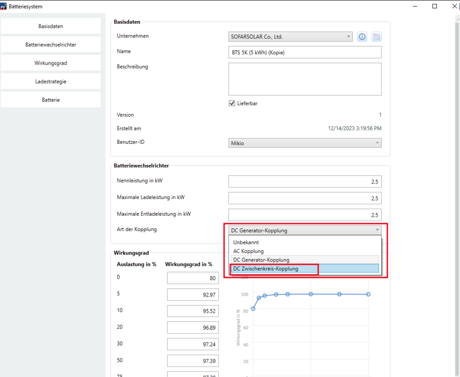
Hallo Thomas Frueh, von uns aus ist leider nur zu sagen, dass wir den Hersteller gebeten haben den Datenbankeintrag zu korrigieren. Solange das noch nicht erfolgt ist, ist der mir bekannte Workaround weiterhin eine Kopie des Batteriesystems anzulegen und dort die Kopplungsart von DC Generator-Kopplung auf DC Zwischenkreis-Kopplung zu ändern. Weiter oben in diesem Thread ist das Vorgehen genauer beschrieben. Viele Grüße Mikio -
Hi Marcelschil, thank you for your post. Unfortunately you can't specify the column format for the export in PV*SOL. But there are several ways to split the first column into a date column and a time column. One way would be to use Excels "Text to Column" feature where you could specify "Space" as delimiter. Therefore you have to add an additional column after the first Date-and-Time column. Then select the Date-and-Time column and head to the "Data" tab where you find the "Text to Column" button which opens a wizard where you can specify the delimiter to "Space" (in the second step of the wizard). Please find a detailed description and a corresponding video on this Microsoft support page: https://support.microsoft.com/en-us/office/split-text-into-different-columns-with-the-convert-text-to-columns-wizard-30b14928-5550-41f5-97ca-7a3e9c363ed7 Hope this helps. Kind regards Mikio
-
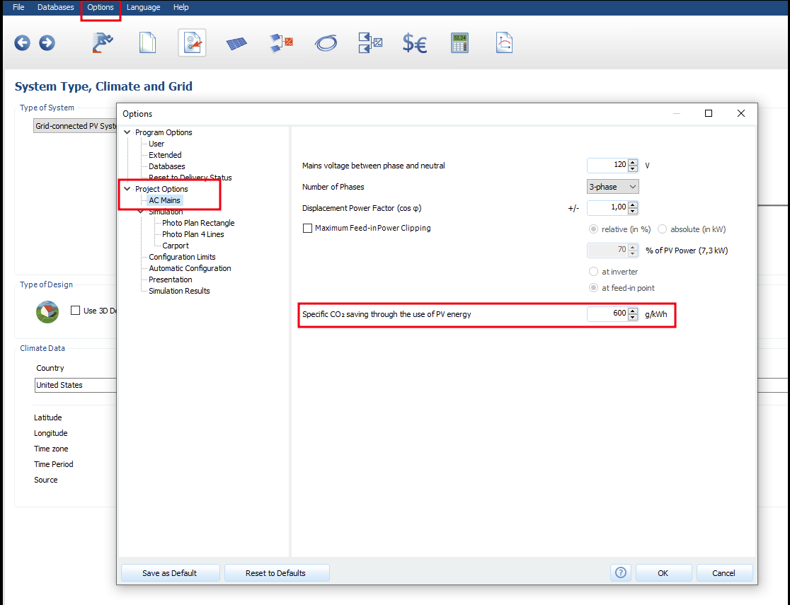
Hi Sunfactor, thanks for the question. The specific CO2 emissions can be set in PV*SOL via "Options > Project Options > AC Main" in the last row ("Specific CO2 saving through the use of PV energy"). Kind regards Mikio

-
Hallo allegro2401, vielen Dank für die Rückmeldung und schön, dass es gut geklappt hat. Die Modulverschaltung wird im 2D Teil von PV*SOL gemacht (nach dem Verlassen von Photo Plan), unterscheidet sich aber nicht vom Verschaltungsdialog in 3D. Sie können nach dem Schließen von Photo Plan direkt auf die nächste Seite "Wechselrichter" wechseln. Ich hoffe das war auch Ihre Frage. Falls nicht melden Sie sich gerne nochmal. Vielleicht hilft auch unser Photo Plan Beispielprojekt weiter, dass auf der Willkommensseite in der rechten Spalte unter "Photo Plan" in den Beispielprojekten zu finden ist. Eine Beschreibung zu Photo Plan sowie eine Videoanleitung auf Englisch finden Sie in unserer Onlinehilfe unter: https://help.valentin-software.com/pvsol/de/navigationsseiten/pv-module/photo-plan/ Viele Grüße Mikio

-
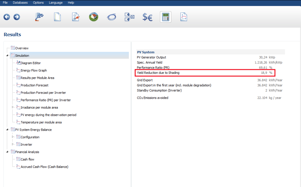
Hi Rene, for large 3D projects, we recommend to split it into sub-projects with less than 10.000 roof parallel modules respectively 7.500 inclined modules. A higher number is not possible in the 3D planning. Alternatively, we recommend to pick a representative small part of the system, simulate it in the 3D environment to get the value for the "Yield reduction due to shading" in percent and then scale it to the desired number of modules in a new 2D project. Please find further description of this process in this post: Kind regards Mikio
-
Stromtarife für Haushalt und Wärmepumpe HT/NT getrennt aufführen
developer_mo replied to Vondersingold's topic in PV*SOL
Hallo Ralph, das ist richtig. Als Bezugstarif kann nur ein Tarif gewählt werden. Wenn als Anlagenart "Netzgekoppelte PV Anlage mit elektrischem Verbraucher und thermischem System" gewählt wurde, ist es möglich einen Bezugstarif und einen Wärmepumpen-Tarif anzugeben. Wenn die Wärmepumpe aber nur als Verbraucher definiert wurde, kann nur der Bezugstarif angegeben werden. Viele Grüße Mikio -
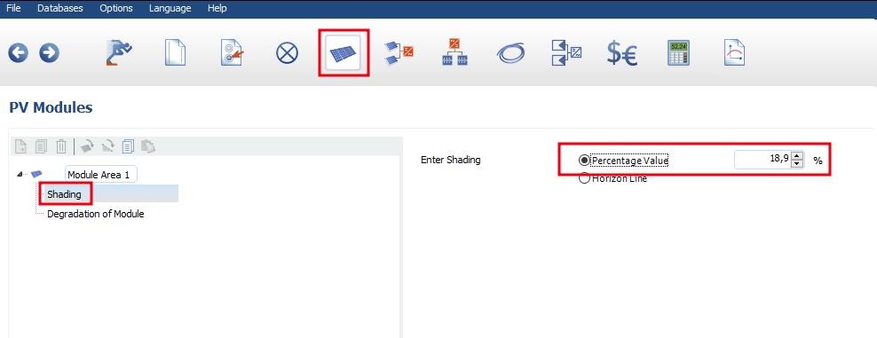
Hi aleksandar.vajs, thanks for your questions. In the 3D environment it is not planed to support more than 10.000 roof parallel Modules. For large roof parallel systems we recommend to split the system into sub-projects. For mounted open space systems we recommend to pick a small representative part of the system with less than 7.500 modules, simulate it to get the value for the "Yield reduction due to shading" in percent and then switch to a new 2D project. In the 2D projects it is possible to simulate up to 100.000 modules per module area (the number of module areas is unlimited). In the "PV Module" section of the 2D project on the left panel under "Shading" you can enter the shading value in percent, that you calculated before. PV systems with tracking in the 3D environment will probably not be implemented. The cost of implementation exceeds the benefits and the demand for PV systems with tracking is also low. For the creation of PV systems with tracking, 2D planning must still be used. I am unsure whether I have understood your question correctly. Net-Metering can be selected in PV*SOL in the "Financial Analysis" section under "Energy Balance / Feed-in Concept". Further information can be found in our corresponding online help section https://help.valentin-software.com/pvsol/en/pages/financial-analysis/#economic-efficiency-calculation-grid-connected. Does that answer your question or do you mean a specific functionality in net metering? Kind regards Mikio

-
Keine "Kabelknoten" im Kabelplan wenn Option "Polystring" aktiv
developer_mo replied to SMARTechSolar's topic in PV*SOL
Hallo Patrick, leider ist Frederiks Antwort weiterhin aktuell. Das heißt, dass wir weiter an einer neuen 3D Umgebung arbeiten und die Überarbeitung der Polystring-Verschaltung nicht vorher kommen wird. Viele Grüße Mikio -
Hallo Jan, ich kann verstehen, dass es unschön ist die Daten in ein anderes Dokument zu übertragen. Leider kann ich zu diesem Featurwunsch trotzdem noch nichts neues sagen. Da andere Features höher priorisiert wurden ist noch nicht sicher ob und wann eigene Vorlagen für die Präsentation in PV*Sol eingebaut werden. Viele Grüße Mikio
-
Hi José Carlos, thanks for your report. I compared a south hemisphere animation with one in the north but I couldn't find implausibilities. In the south hemisphere the sun at noon is in the northern sky as expected. Could you describe the problem you are experiencing in more detail? I looked at the course of the equator on Wikipedia and saw that it runs through northern Brazil. If your location in Brazil is north of the equator, this could be the reason why the animation behaves as it does in the northern hemisphere. Kind regards Mikio
-
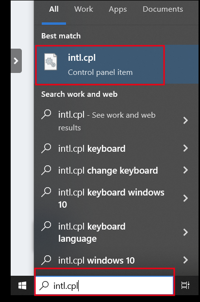
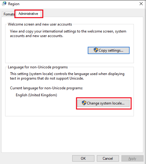
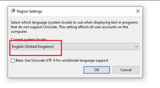
Hi Ihor Kruhlov, thank you for reporting this problem. You are right, there are some problems with the characters "ä, ü, ö and ß" in Photoplan. We are working on a solution to fix this issue. For now, the problem can be avoided if "ä, ü, ö and ß" are not used. This is the easiest way. Another way, which should work on most PCs (but includes a reboot of your PC) is to change the Windows "Region Settings" to German or English. Here is an instruction to change the Region Settings: 1) Please press the Windows Key and type "intl.cpl" into the Windows search bar and click on "intl.cpl Control panel item" to open the "Region" dialog. 2) Next, click on the "Administrative" tab and then on "Change system local". 3) Finlay in the "Region Settings" dialog, please change the language to English (UK or US) or "German (Germany)". After the change you have to reboot your PC. Kind regards Mikio
-
How to add module with inclination on wall
developer_mo replied to abdullah.alamin's topic in PV*SOL
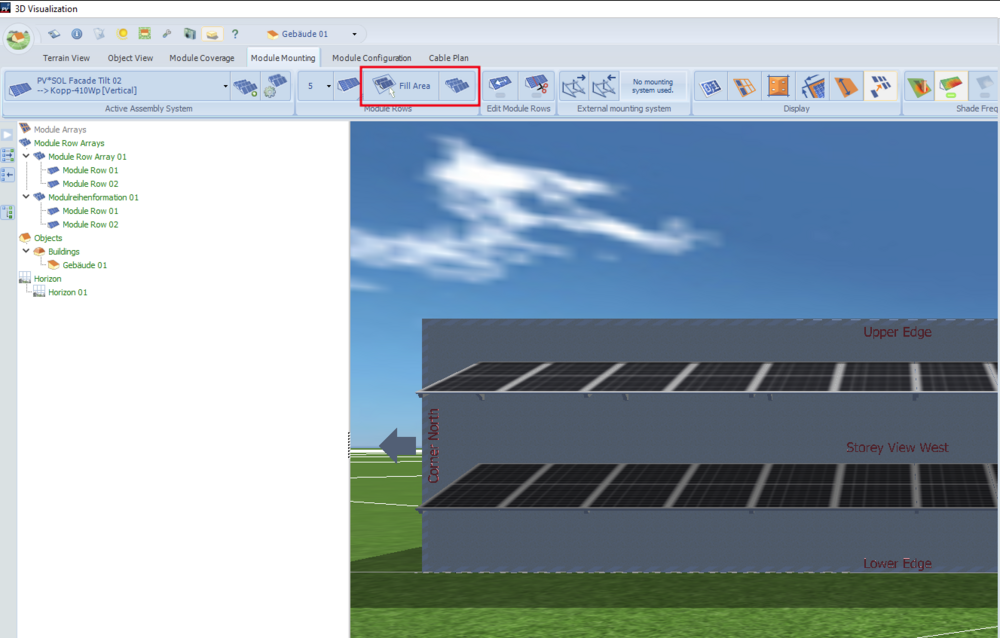
Hi abdullah.alamin, thank you for the question. Do I understand correctly that you want to incline the modules to 70 degree? If so, you can achieve this as follows: Activate the 'Module Area' and go to the 'Module Mounting' tab. Next, click on 'New Assembly System' and on 'PV*Sol Facade Tilt'. If not already done, select a module by clicking on 'New Module'. Then you can specify the 'Mount Angle' in the 'Orientation' section. After confirming with 'Ok', you can create the module array as usual and it should be tilt up to the specified 'Mount Angle'. Here are some screenshots of the process: In our online help you can find further information about the calculation of inclined bifacial modules: https://help.valentin-software.com/pvsol/en/calculation/pv-modules/bifacial-modules/ Kind regards Mikio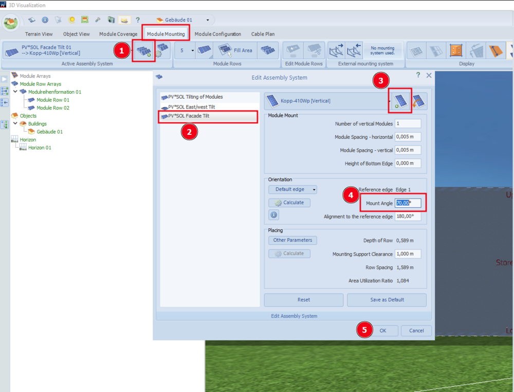
-
Hi omid, thanks for your question. Based on the scenario and the diagram I would assume following possibilities that causes the relatively low charging of the battery by the pv system: 1) the consumption takes almost all PV energy on the majority of the days 2) the battery gets less charging by PV energy because the it is full or almost full at the times when pv energy is available Of course, there could also be other reasons, such as the possibility that not all of the PV energy is available for charging the battery. For the scenario you're describing, I think it is plausible that the battery is mostly charged from grid because it is charged as much as possible every night. The Time-Controlled Charging in PV*Sol can only be set for the whole year and is not adaptable to changing seasons. So it is not possible to charge the battery to a lower SOC only in summer. If adaptability to season would help, I could forward it as a request to the developers. If the reason is still unclear, feel free to share the project file in the post or send it via private message in this forum. Kind regards Mikio
-
Hi Powerix, unfortunately it isn't and I still can't specify when this feature will be available. Kind regards Mikio
-
Batteriesystem - Zentraler Anschluss des Batterispeichers
developer_mo replied to mdeniz17's topic in PV*SOL
Hallo mdeniz17, hier noch ein Nachtrag: laut Betriebsanleitung sollte das Batteriesystem ausschließlich als Zwischenkreis-Kopplung angeschlossen werden. Die DC Generator-Kopplung, die in der Datenbank eingetragen wurde ist also nicht korrekt. Unser Datenbank Team hat den Hersteller kontaktiert und darum gebeten, den Eintrag zu korrigieren. Bis die Korrektur erfolgt ist, hoffe ich, dass die oben beschriebene Methode über die Kopie des Batteriesystems eine gangbare Alternative ist. Viele Grüße Mikio -
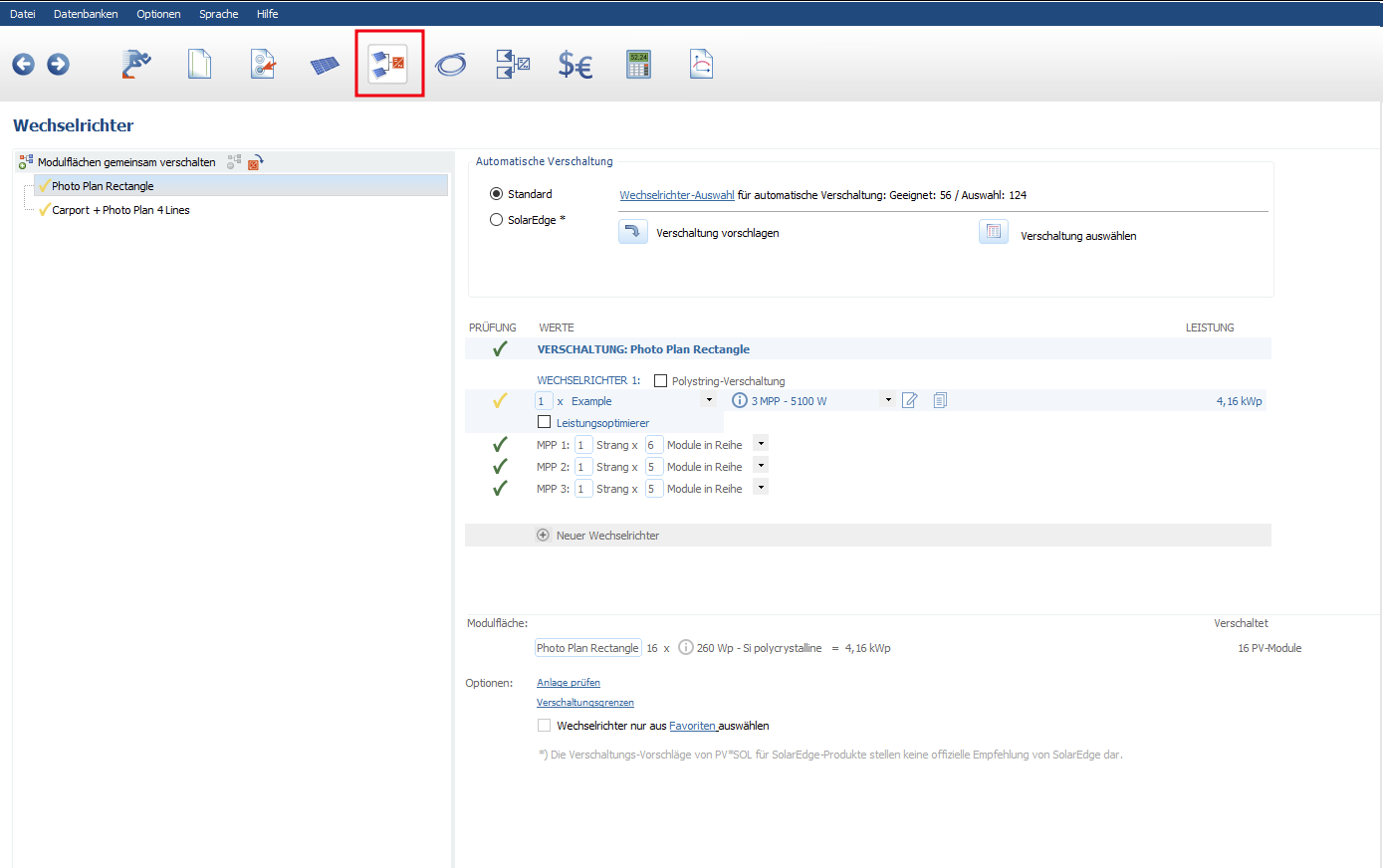
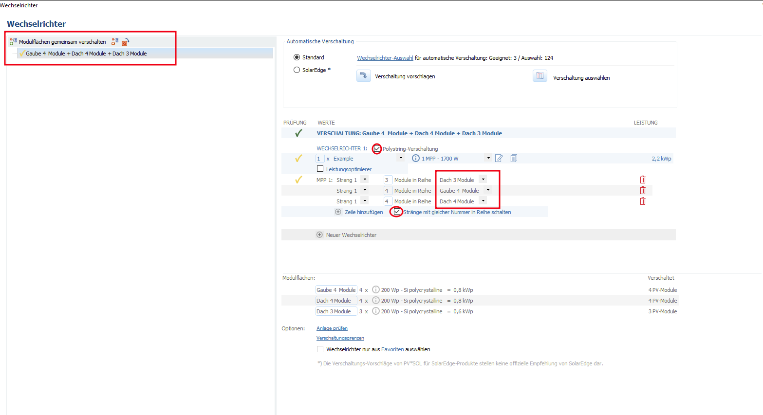
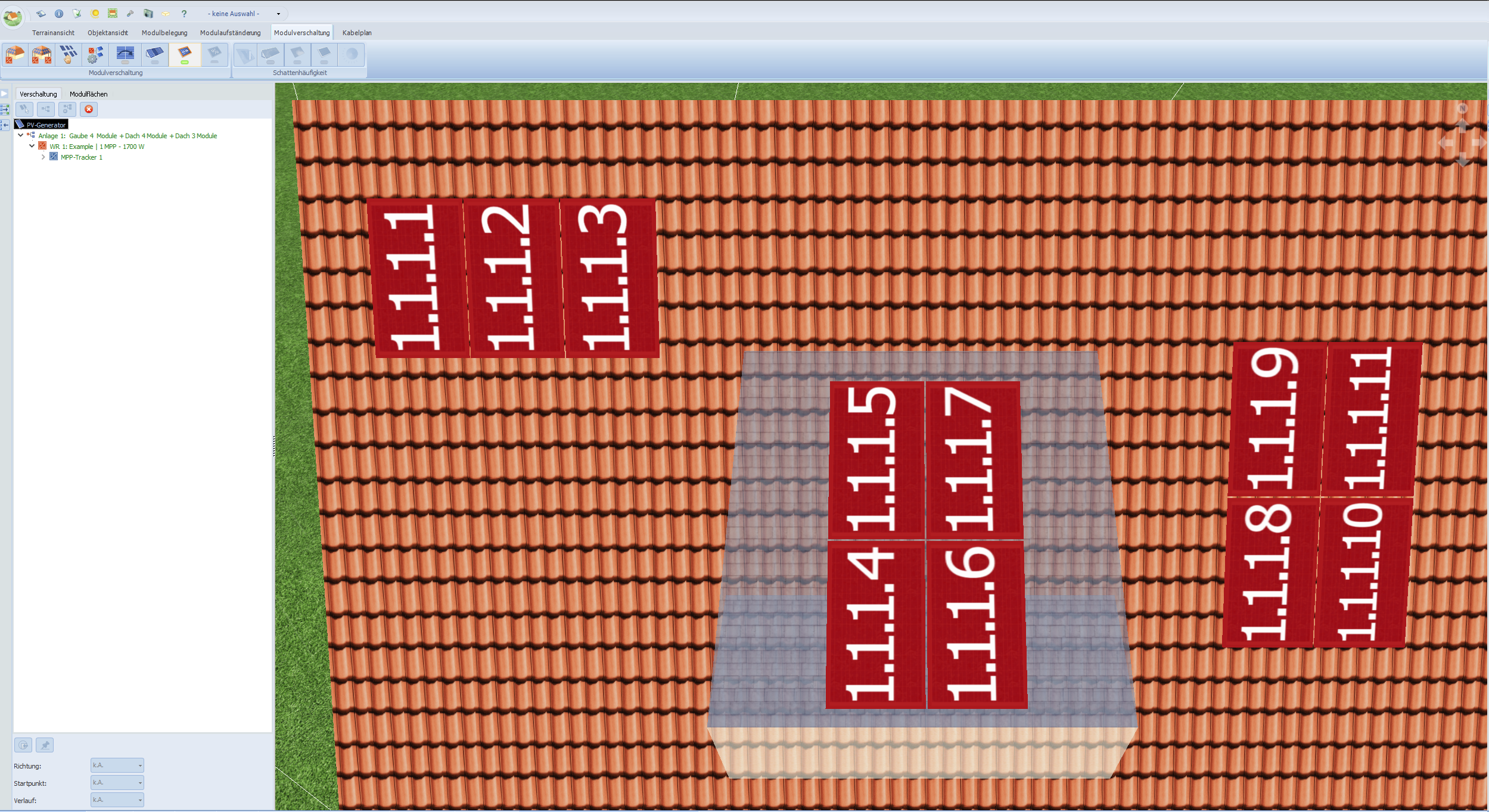
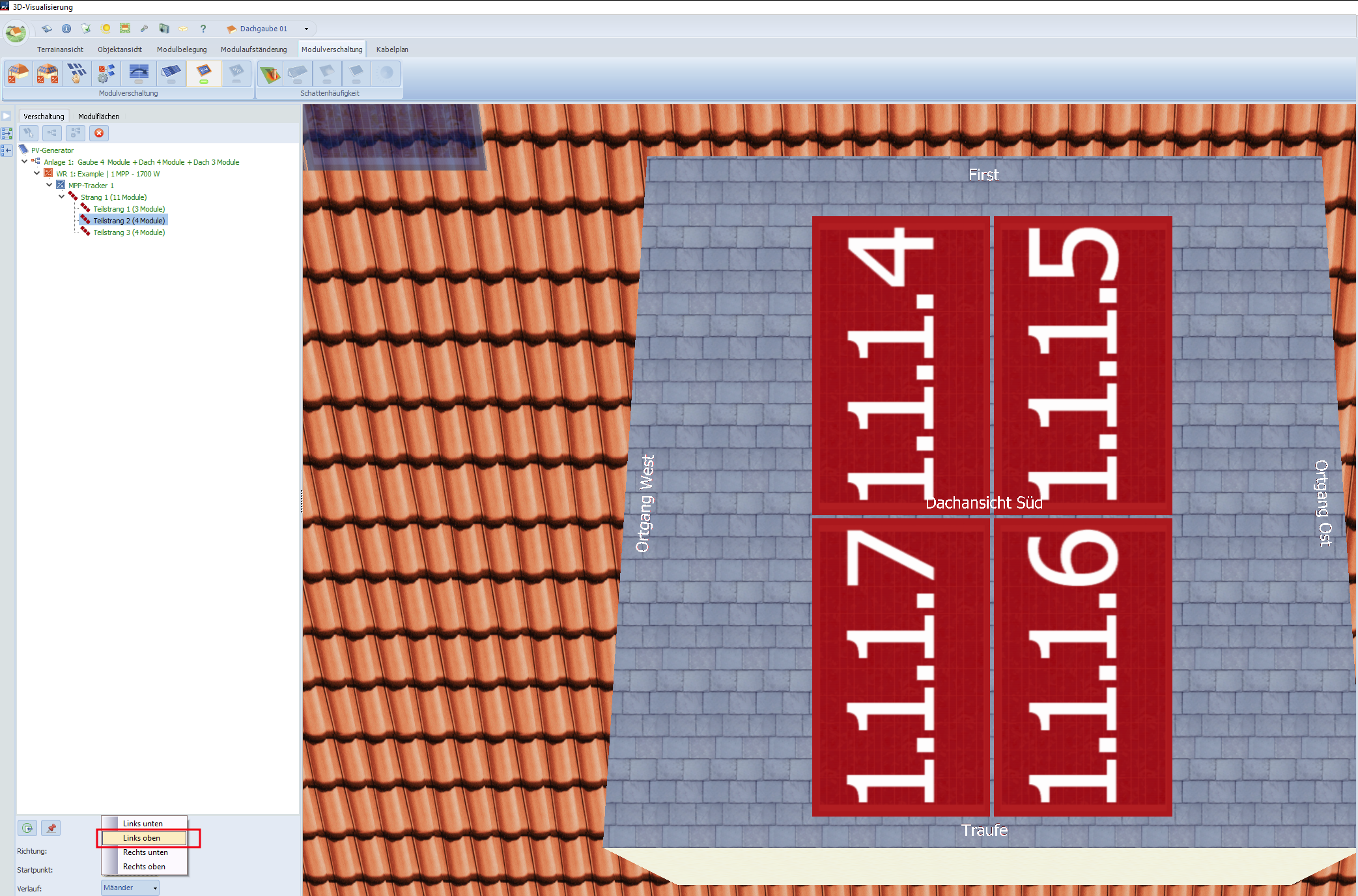
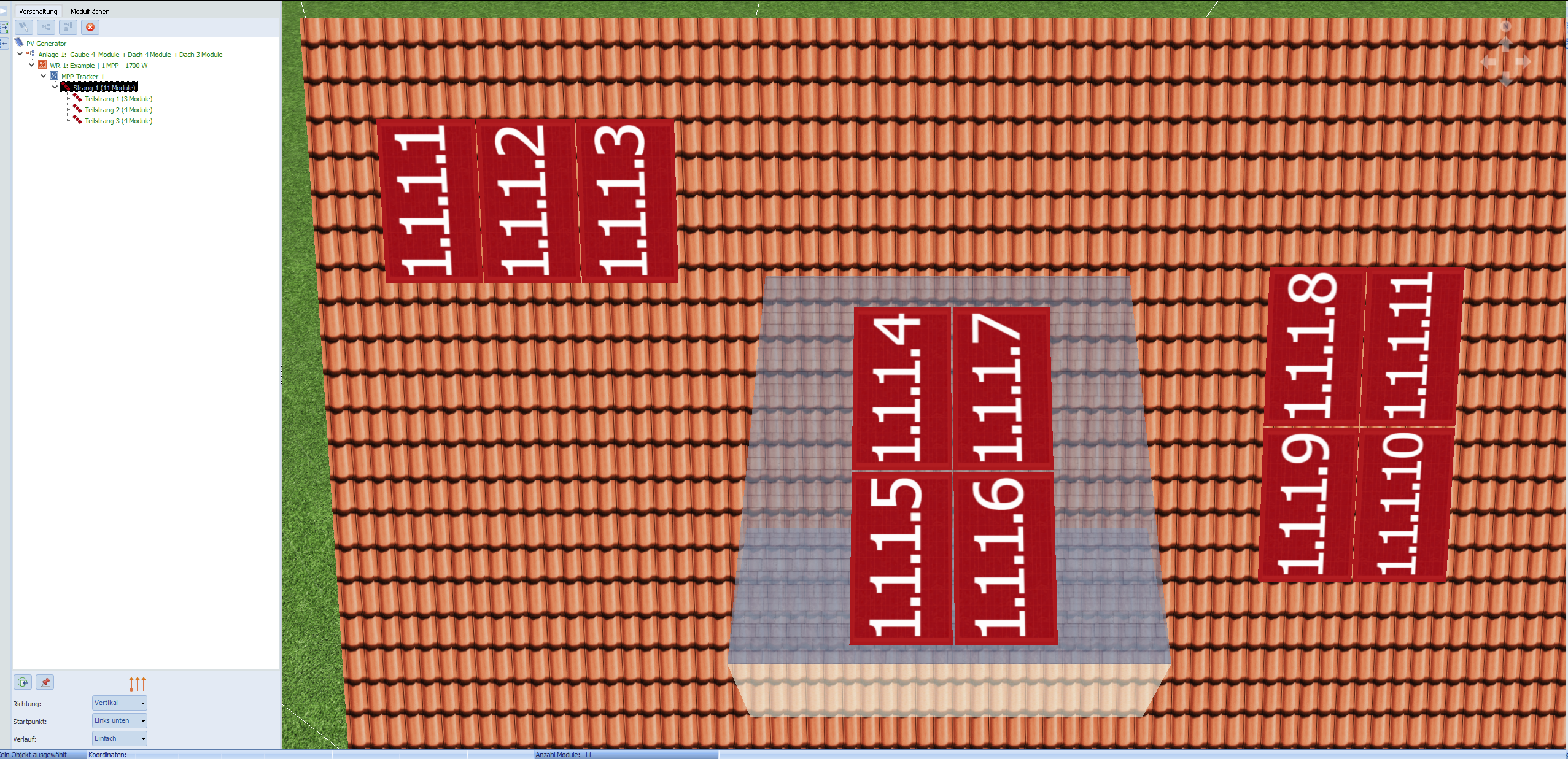
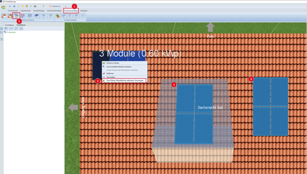
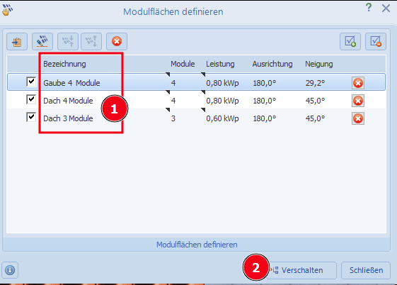
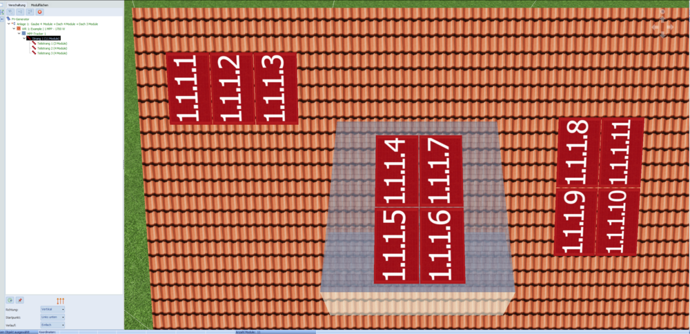
Hallo mdeniz17, vielen Dank für den Beitrag. Ich nehme an das Ziel ist es, beispielsweise oben links zu beginnen, dann die Gaube einzubeziehen und dann bei der Modulfläche unten rechts zu enden. Also, dass die Module auf Ihrem Bild mit den Nummern 4, 5, 6 und 7 auf der Gaube sein sollen. Leider ist es nicht möglich, die Module zwischen unterschiedlichen Modulflächen zu verschieben. Das heißt, die Reihenfolge muss leider schon beim Verschalten so wie sie später sein soll angelegt werden. Für Ihr Beispiel könnte das wie folgt gemacht werden: Die Modulflächen der Reihe nach auswählen und über Rechtsklick "Zum Dialog 'Modulflächen definieren' hinzufügen' klicken. Dann den Dialog "Modulflächen für die Verschaltung definieren" auswählen (Nummer 5). Im "Modulflächen definieren" Dialog am besten die Modulflächen gleich umbenennen, sodass aus dem Namen hervorgeht, um welche Fläche es sich handelt und auf "Verschalten" klicken. Im folgenden Wechselrichter Dialog, dann mit Strg + Klick alle drei Modulflächen markieren und auf "Modulflächen gemeinsam verschalten" klicken. Wie Sie es in Ihrem Projekt vermutlich schon gemacht haben, können Sie nun "Polystring" und "Stränge in Reihe schalten" wählen und zwei neue Zeilen hinzufügen. Jetzt ist es wichtig, dass die Modulfläche bei der die Verstringung beginnen soll in der ersten Combobox ausgewählt ist und die korrekte Reihenfolge fortgeführt wird. Hier Modulfläche namens "Dach, 4 Module" also als erstes, dann "Gaube, 4 Module" und dann "Dach, 4 Module. Nach Bestätigung mit Ok sollte es in etwa so aussehen: Um jetzt noch die Reihenfolge der Module auf den einzelnen Modulflächen anzupassen, können diese entweder mit der Maus verschoben werden oder der Startpunkt für jede Modulfläche über das Menü an der linken Bildschirmseite geändert werden. Das Endergebnis würde dann beispielsweise so aussehen: Einen einfacheren Weg kenne ich leider aktuell nicht. Ich hoffe das hilft trotzdem weiter. Viele Grüße Mikio


-
How to control the Charge of Electric Vehicle values?
developer_mo replied to obikerui's topic in PV*SOL
Hi again, the next release (PV*Sol Premium R3) that fixes this issue will be released next week. Presumably on December 19th 2023. Kind regards Mikio -
Batteriesystem - Zentraler Anschluss des Batterispeichers
developer_mo replied to mdeniz17's topic in PV*SOL
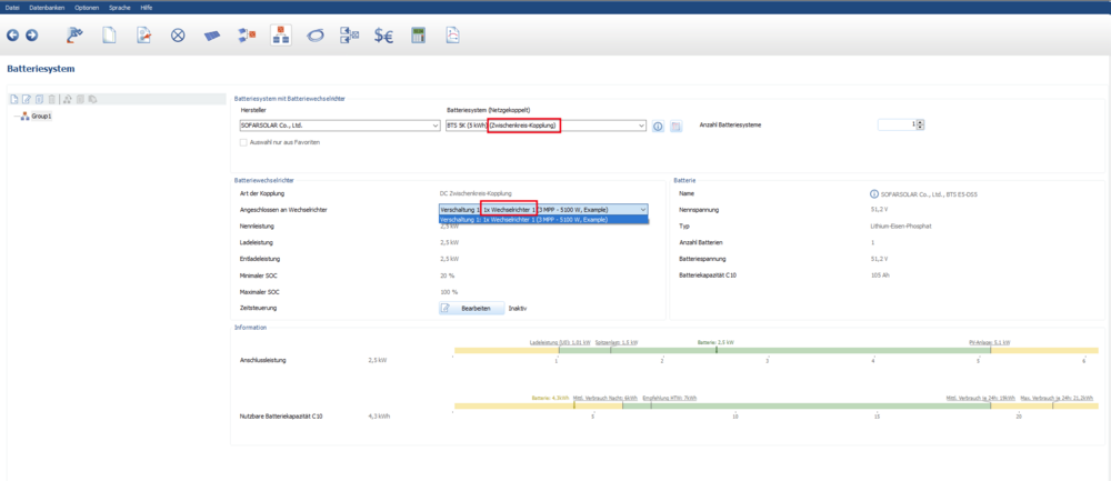
Hallo mdeniz17, vielen Dank für die Frage. In diesem Fall sollte die Anbindung des Batteriesystems als DC Zwischenkreis-Kopplung weiterhelfen, wenn ich Ihre Frage richtig verstehe. Da die Batterie in der Datenbank aktuell als DC Generator-Kopplung eingetragen ist, müssten Sie als erstes eine Kopie des Batteriesystems anlegen und die 'Art der Kopplung' von DC Generator-Kopplung auf DC Zwischenkreis-Kopplung ändern. Wenn Sie die geänderte Kopie des Batteriesystems dann als Batteriesystem ausgewählt haben, können Sie nicht es nicht mehr einzelnen MPP's zuweisen sondern es ist direkt an den Eingang des Wechselrichters angeschlossen. Ich hoffe das hilft weiter. Viele Grüße Mikio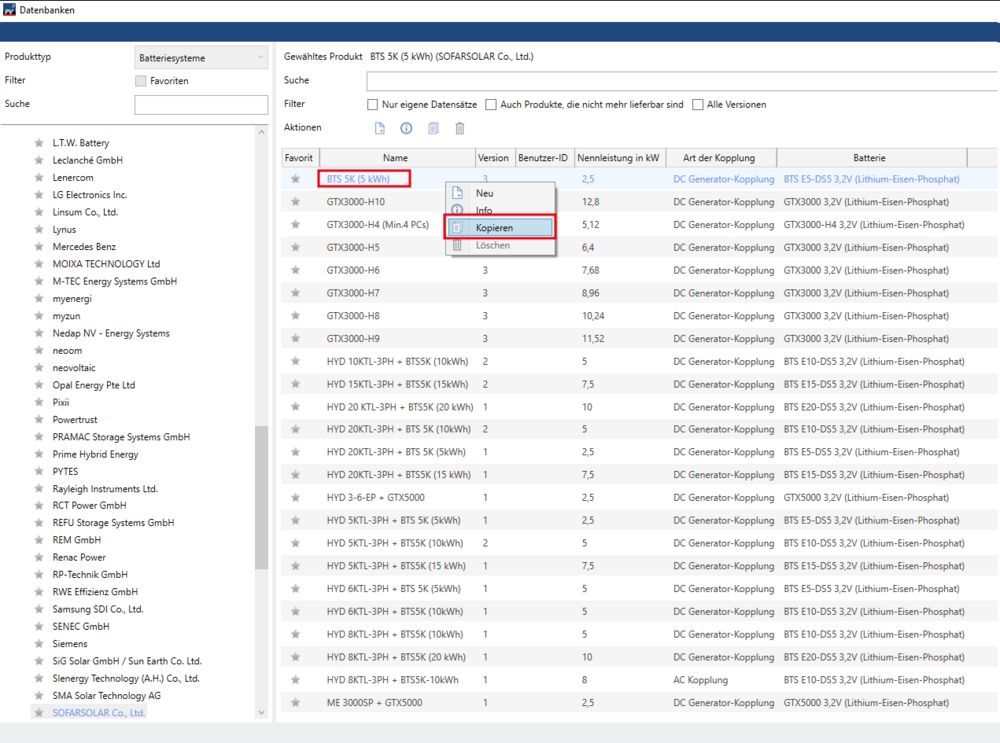
-
Hallo Flo, vielen Dank, ich habe die Projektdatei erhalten und konnte das Problem nachvollziehen. Nach Rücksprache mit Kollegen habe ich den Grund herausbekommen: Der Wechselrichter an dem die Batteriesysteme hängen, wird von der Simulation als primärer Wechselrichter betrachtet. Das heißt er wird zuerst zur Deckung des Verbrauchs herangezogen. Besteht also zu einem Simulationszeitpunkt Bedarf, so wird dieser erst von diesem Wechselrichter gedeckt. Bleibt dann noch PV-Energie übrig, so wird diese zum Laden der Batterie verwendet oder eingespeist. Erst danach werden die anderen Wechselrichter zur Verbrauchsdeckung herangezogen. Im Endeffekt steht dadurch weniger PV-Energie zum Laden der Batterien zur Verfügung. Gerade wenn man einen relativ hohen Bedarf hat, bleibt kaum noch etwas übrig, um die Batterien zu laden. Viele Grüße Mikio
-
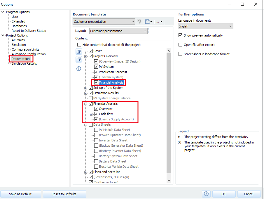
Hi sunil, unfortunately, it is not possible to remove individual table rows from the presentation via the project settings. To remove the IRR, I recommend exporting the presentation as a Word file and deleting the corresponding two lines (under the Project Overview and in the Financial Analysis headlines). If the entire financial part should not be included in the presentation, this can be done via > Program options > Presentation (see screenshot). Kind regards Mikio
-
How to control the Charge of Electric Vehicle values?
developer_mo replied to obikerui's topic in PV*SOL
Hi obikerui, thanks a lot. I received your message with the project file and was able to reproduce the both behaviors (vehicle not charging and skipping result page). We will fix this as soon as possible. I will inform you about the next release under this tread. Kind regards Mikio -
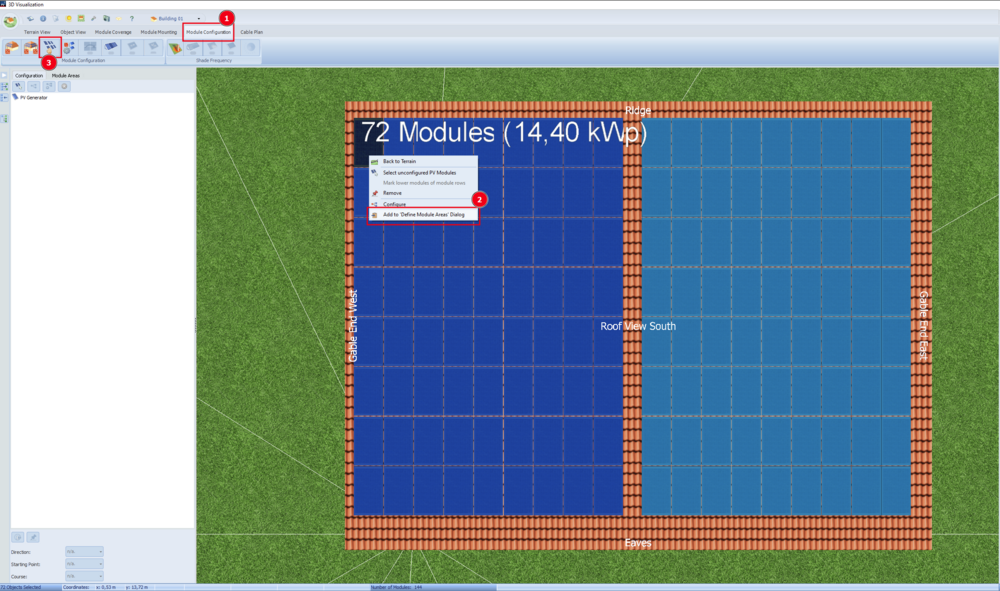
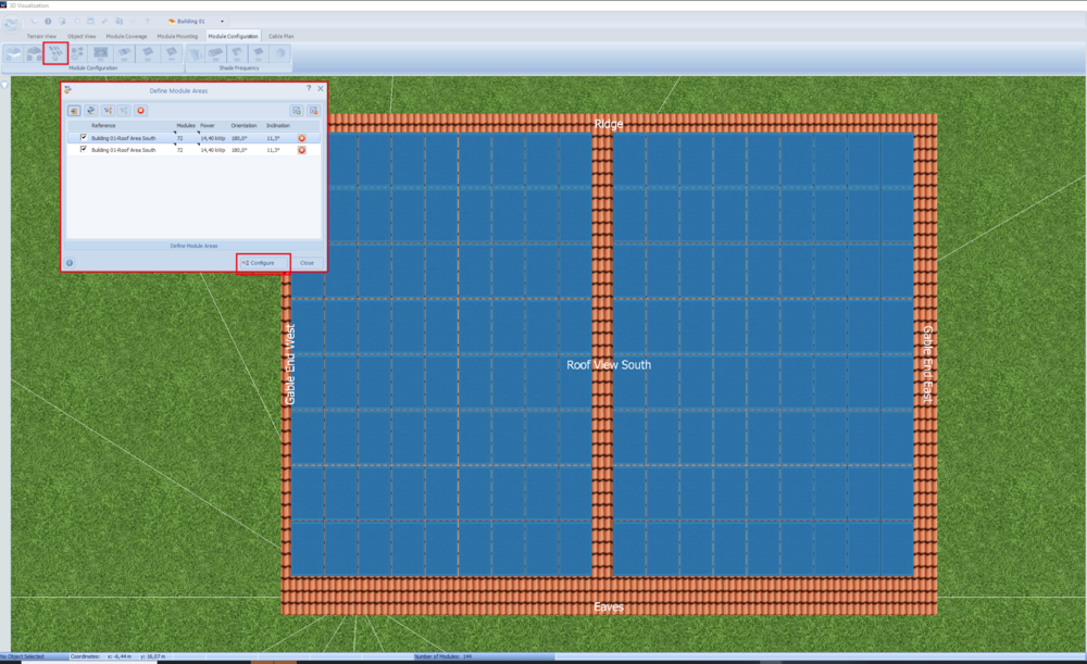
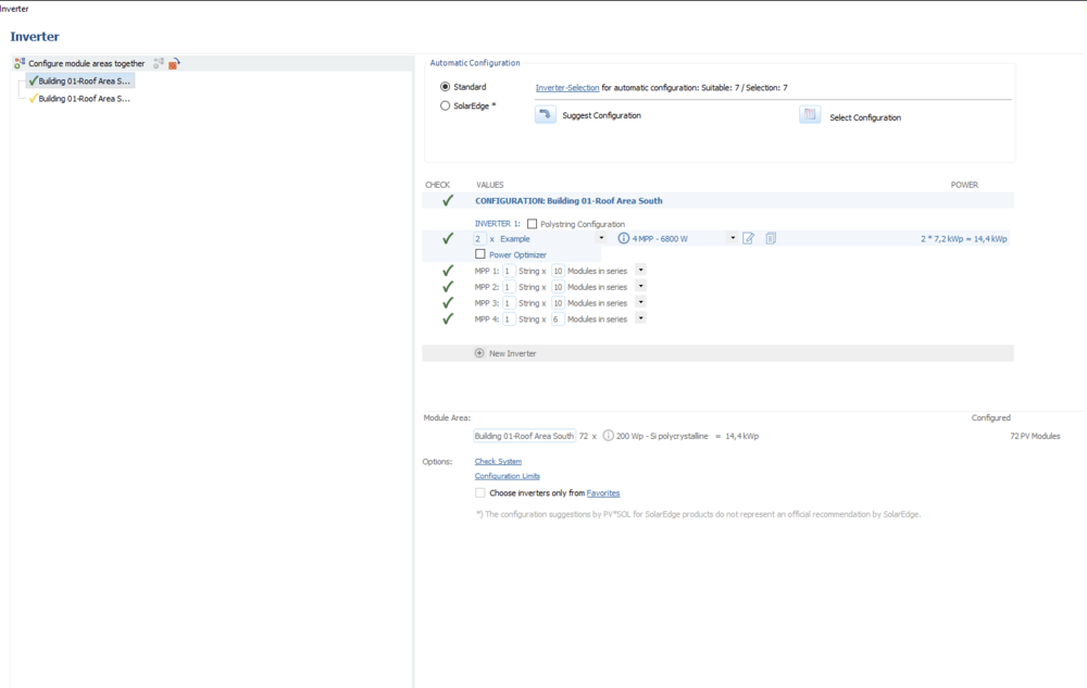
Hi Aman, thank you for your question. To configure modules separately, please select the module array you want to configure (on the "module configuration" tab) and use the context (by right click) to find the option "Add to 'Define Module Area' Dialog". Open the "Define Module Area for Configuration" Dialog from the menu bar. There you will find the selected modules for separate configuration. Here are some screenshots of this process: Does this answer your question? Kind regards Mikio
-
How to control the Charge of Electric Vehicle values?
developer_mo replied to obikerui's topic in PV*SOL
Hi obikerui, thank you for your post. There can be various reasons why the vehicle is not charging. It is difficult to determine the reason for your project from the results. Could you share the project file or send me a private message in this forum? Kind regards, Mikio -
Hallo Flo, vielen Dank für den Problemreport. Ich kenne das Problem noch nicht. Könntest du mir die Projektdatei schicken, damit ich versuchen kann den Fehler nachzuvollziehen? Am besten via privater Nachricht hier im Forum. Viele Grüße Mikio
-
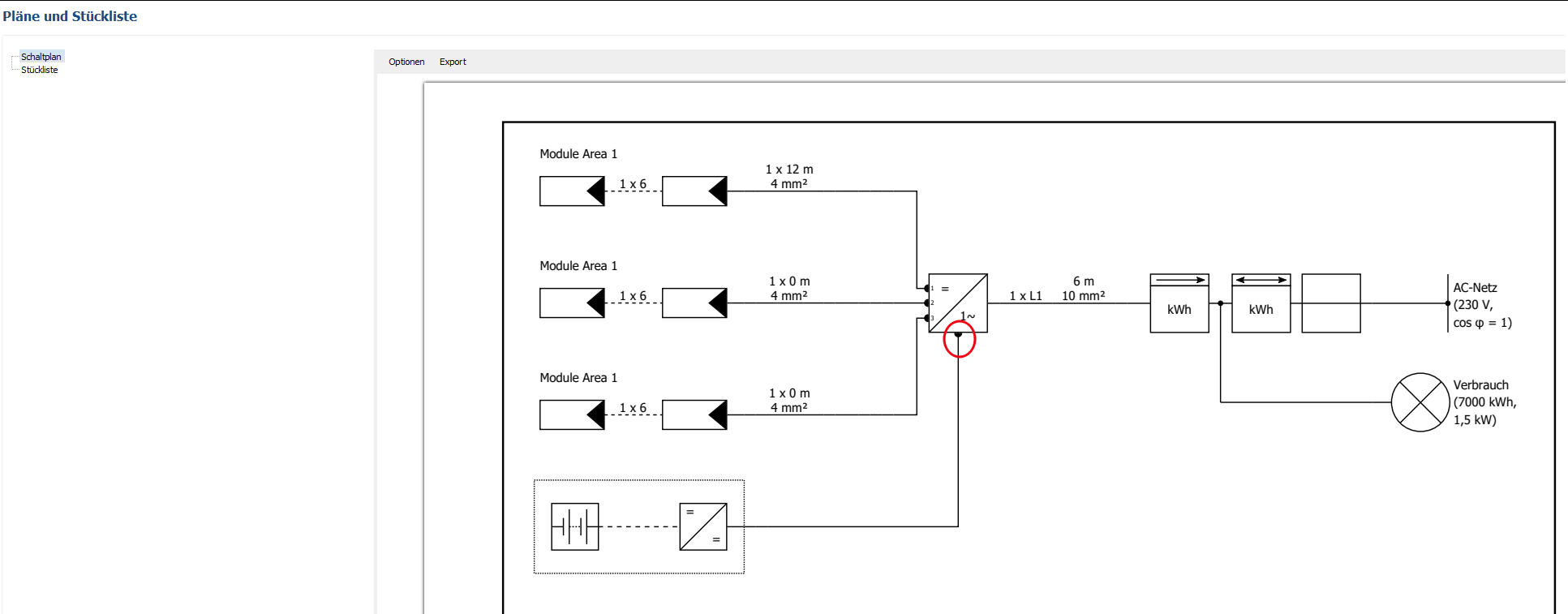
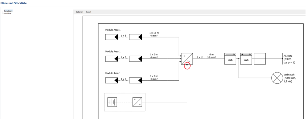
Hi Martijn, thank your for your contribution. It is probably correct that a T-combiner is not necessary for this configuration. In our database entry it is recognized, that the inverter has two different MPPTs. However it is not planned to extend the data model by the number of DC connections, so unfortunately PV*SOL cannot illustrate this at this level of detail. Kind regards Mikio