
Jimmy
Members-
Posts
97 -
Joined
-
Last visited
-
Days Won
29
Jimmy last won the day on May 11 2022
Jimmy had the most liked content!
Profile Information
-
Location
Sweden
Recent Profile Visitors
1,656 profile views
Jimmy's Achievements
-
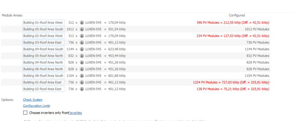
It's easy to get something wrong and not notice when you have this many roof areas and inverters. I usually rename my buildings to make it easier to keep them apart. As a side note: Have you thought about using a central inverter for projects of this size? It should keep the cost down by quite a lot compare to over a dozen SUN2000-196KTL. Huawei doesn't have any bigger (except the 215KTL which is basically the same) but there are plenty of other brands that have inverters that are capable of handling all of these panels on a single central inverter. Might be worth exploring if you haven't already done so.
-
Hi Venco, You've configured it wrong. Building 01 and 02 west and building 01 and 02 east have some modules on the wrong building.
-
With the new Metronorm 8.1 data being available it would be nice to have the pre selected locations that are already available in PVSol updated so that you don't have to create new climate data for locations to go from Metronorm 7 to Metronorm 8.
-
Hi Pietro, @TurtlesOGhad the same problem about a month ago, see the post here:
-
Hi Turtles, You can use the shift of depth to "rotate" them 180 degrees. They are also perpendicular to the reference edge so if you want to rotate them by 90 degrees you'll have to pick the correct reference edge when extruding a building.
-
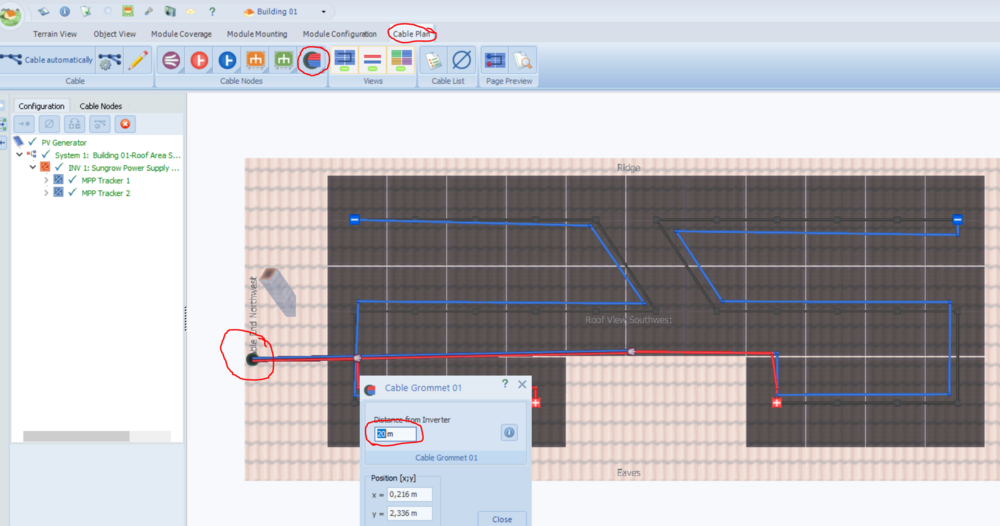
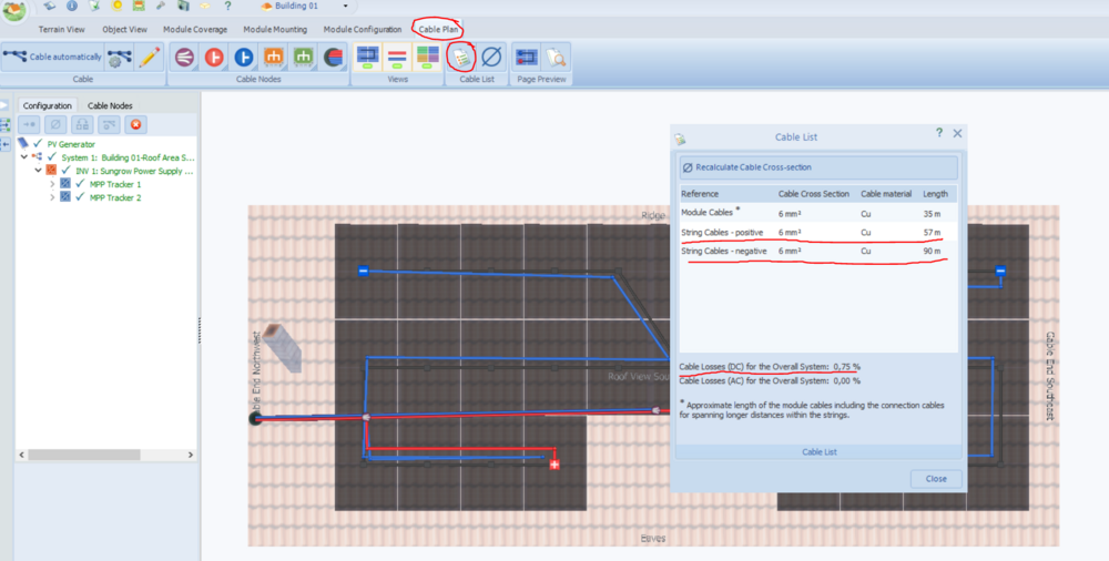
Hi Codrin, As Martin I'm not sure that I understand you correctly but I'll give it a shot anyway. As I understand it you want to place the inverter in the 3D Design and have PV*SOL calculate the cable length based on thee position of the inverter. This is not possible in PV*SOL as the buildings don't have an "inside" in 3D design. When in 3D design - Cable plan you have to input the distance to the inverter from the "grommet" (the place in the roof where the cables will go down). This basically only gives you the cable losses and the possibility to see cable length (including the cable length you input as distance from the grommet to the inverter) If you want this information in the schematic you will have to input it yourself as far as I know. Best regards
-
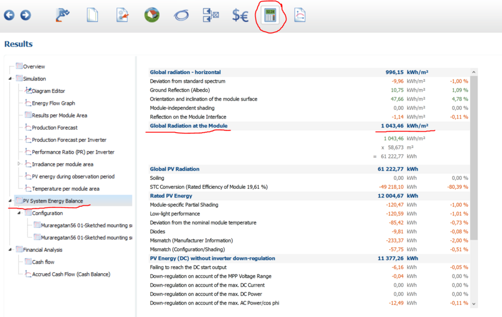
Hmm... I'm thinking that there has to be some fundamental flaw in how this project is setup since all of my installations are pretty close to accurate when comparing simulation and reality. And since the biggest new factor is imported climate data it should be something with this. When you check the PV System Energy balance, is it the same global radiation at the module as your measurements?
-
Hi, I have a few questions regarding this. I've never input climate data myself so there might be a few things that I don't understand about this. But anyway. A few things stick out to me as worth mentioning/questioning. 1. The simulation is done in 1 hour steps while I assume that the data is in minute steps. 2. If precise radiation values are recorded and used, should the albedo really be set to 20%? Seems like the climate data has already accounted for albedo and that we're adding another 20% on top of actual values. I'd also be very interested to know the precise setup of the system. What panels, inverter and cables are being used. How old are the panels and have they been checked that they actually produce their nameplate under STC? Lastly I want to mention the possibility about shading of the system being larger than the shading of the sensor and how that might affect the simulation since I assume that shading environment and horizon were not 100% accurate (if modeled at all). Just a few thoughts.
-
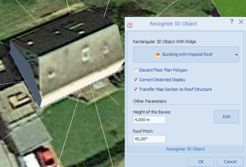
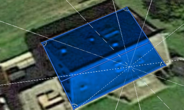
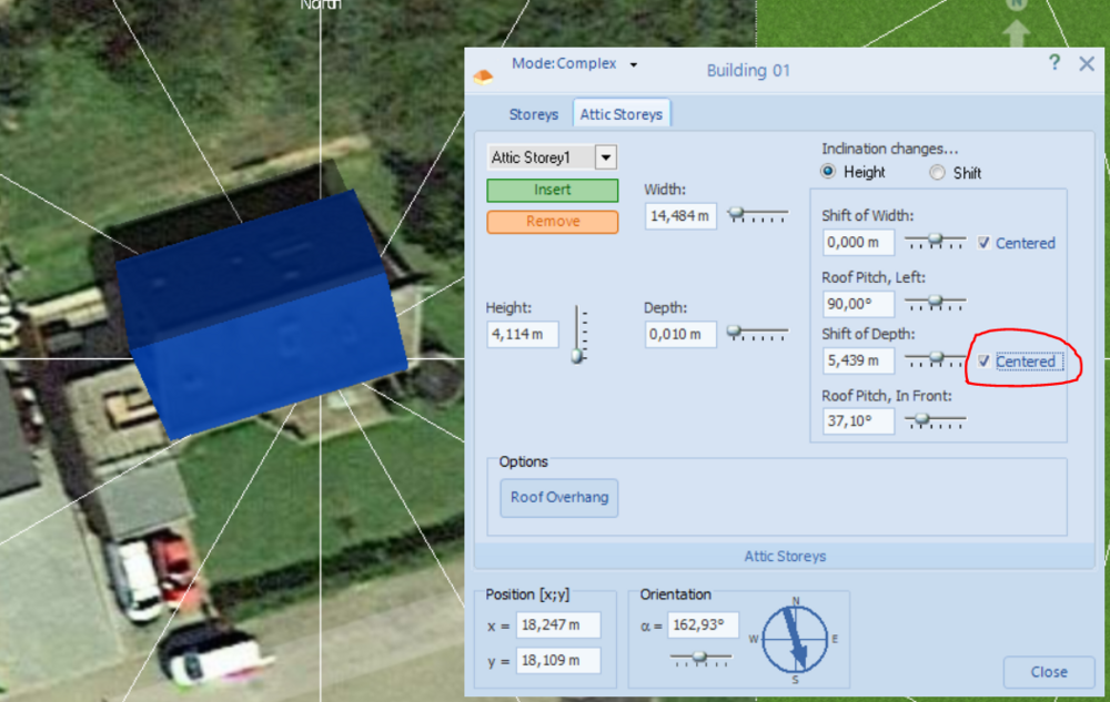
Extract the building as a "hipped" or "tented" roof instead of a "gabled roof" to get unique textures on each side, like this: Note that the distortion isn't corrected well when doing this but it's better than no texture. Also, in the case above I had this image originally: Note the placement of the line in the middle that it is not center and that it follows the roof ridge to get the textures on each side as in the first image. This will need to be corrected since both roofs are the same size but the angle makes the north seem larger. Press the edit button while extracting the building and then center the shift of depth like so:
-
Hi SP, Yeah, you're not the first. Here's a tread about it: I haven't had these problems myself so I'm afraid that I can't offer any first hand experience. Best regards
-
I think it should be the "PV Generator Energy (AC Grid)" with a slight rounding error, at least that's what I get. But if you're using 470g/kWh I can't make sense of your numbers.
-
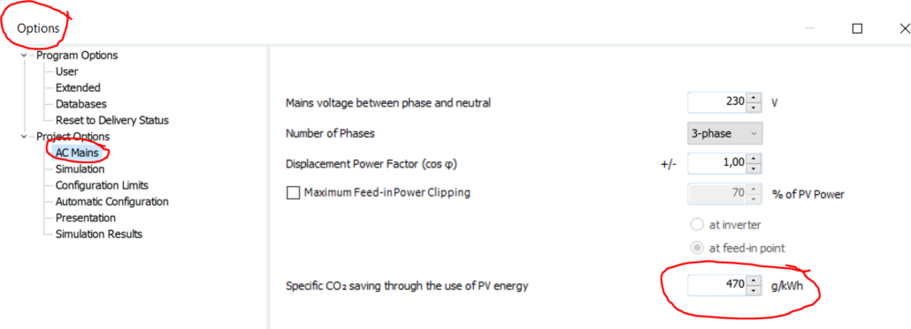
Hi obrvaner, Yeah, the calculation is just as simple as g/kWh and you have to input that yourself based on your region and and LCA for the system. You can change it here: And I just want to add, in regards to what Martin said above about how dirty our electricity in Sweden is that the calculation is wrong because those are our total energy emissions calculated on electricity production. And electricity only stands for about 9% of our emissions. We're about 30g/kWh, second cleanest electricity in Europe I believe. Which, coupled with the most reliable LCA I've read (assuming that the panels are made in China) doesn't really guarantee that solar in Sweden is a net positive for the climate. I don't tell my costumers this as they're not really after the environmental benefits but rather the economical and if they want to feel like they're doing the climate a great service at the same time I'm not going to burst their bubble.
-
I've been using PV*SOL for years now and it always bothered me that creating complex buildings and shapes is such a hassle and really hard to get good when it comes to accuracy and appearance. So for more than 6 months I've been, on and off, developing a reliable process to create accurate 3D models from drone fotage. You can see an example of an area I made last November here: So, anyway. Up until now my requirements for the drone photos have been very strict in how they need to be captured which has resulted in me needing to do it all myself to get the quality to a satisfactory level to be used in PV*SOL. Well, I think that I've found a way around that and I'd like to test if I can create sufficiently good models from drone photos taken by someone who doesn't understand the process of creating the models. All I ask in return is some feedback on the models. Requirements: * Drone - Doesn't really matter but it's good if you have an enterprise drone. * PV*SOL Premium 2022 Process: * Take at least 400 (preferably not much more than 1000) pictures of the object that you want modeled. * Use as high resolution as you can * If you know a lot about photography try to get the photos with as much sharpness and contrast as you can. If you don't know a lot just leave the drone on auto settings. * Have a large overlap with the pictures. Generally flying over a building at medium speed and using the auto function to take a picture every 2-3 seconds is good enough. * Make sure to take pictures from multiple angles * Shift the pitch of the gimbal (change the camera angle up/down) by 20 degrees 2 or 3 times. Start looking straight down (-90 degrees) and photo the entire building with a large overlap. Then go around the building with a -70 degree camera angle, and then -50 degrees. The above instructions are guidelines, they aren't super strict but are a compromise between what I need and simple instructions. So yeah, first 3 people to reply to this post that they're interested will get a 3D model of a complex building if they want and can provide drone fotage. I'll do my best regarding quality but since this is a test I can't make any promises. And as I said, all I ask in return is some feedback.
-

Dimensioning fields for buildings/windows etc malfunction
Jimmy replied to Lukas Bernhard's topic in PV*SOL
Hi Lukas, I import a lot of 3D models and I've never encountered this. What strikes me as very odd, other that the orientation, are the other values in your screenshot. A building height of 17155 meters and the resulting x/y position are most likely way outside of what PV*SOL can handle. Have you tried to reduce the scale of the object significantly?


