


developer_mh
-
Posts
1,855 -
Joined
-
Last visited
-
Days Won
173
Posts posted by developer_mh
-
-
Hi Stuart,
I am very sorry, but no, right now we have no updates on that topic. We are ourselves figuring out the best solution. Perhaps you find a tutorial on youtube on that topic that works for you. Try searching for "Extract 3D from Google Earth" or something like this. But we'll keep you updated as soon as we have any news.
Cheers,
Martin
-
Hi Tobias,
herzlichen Glückwunsch zu dem spannenden Masterarbeits-Thema!
Ja, mit einem importierten 3D Modell lässt sich das natürlich schnell lösen, super. Dass es danach alles unterschiedliche Belegungsflächen sind, lässt sich nicht verhindern. Die Verschatlung wird dann natürlich etwas hakelig mit 200+ Belegungsflächen. Mein Vorschlag wäre daher, einen Fassadenabschnitt von vielleicht 10 Modulen exemplarisch korrekt zu verschalten und zu simulieren. Dann importierst du eine Kopie des Gebäudes, in der die Fassedenelemente alle die gleiche Ausrichtung haben, belegst die wieder mit den 10 MOdulen, verschaltest sie (als eine Modulfläche) und schaust dir den Ertragsunterschied an. Dann belegst du die ganze Fassade der Kopie des Gebäudes mit gleich ausgerichteten Modulen, verschaltest sie, simulierst und machst eine Abschätzung der Ertragsänderung anhand deines 10-Modul-Beispiels. So stark sind die Module ja nicht aus der senkrechten gedreht, ich denke, das sollte so gehen.
Beste Grüße,
Martin
-
Hi Josefine,
if you select all inverters of the database, it will very likely be too much for your computer. Try to deselect everything first (by clicking on "Selection" and then "Deselect all"):
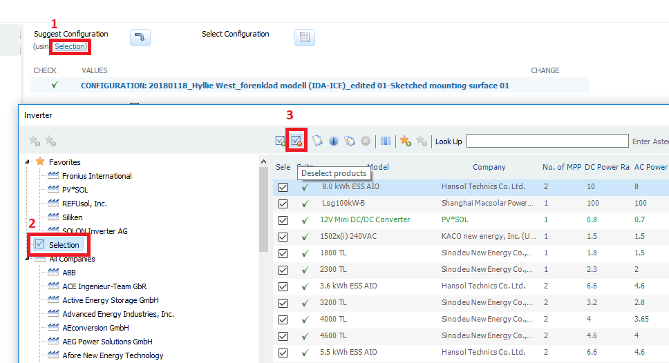
And then choose one or two inverter manufacturers only and select all their models:
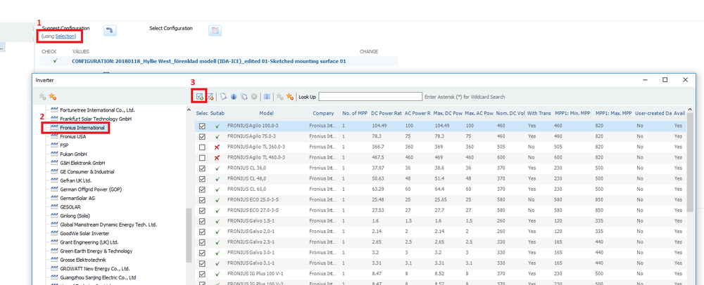
Then you can auto search for a configuration without a problem:

Hope that helps! Kidn regards,
Martin
-
Hi Stuart,
we used to use AutoDesk Remake some months ago while we developed and tested the new feature, but this software is not useable anymore. They also changed the license and so on, so we had to evaluate other alternatives. The colleague who evaluated these tools (i.e. tools to make 3d models out of GoogleEarth Pro to import them into PV*SOL) returns next week from holidays, so he will answer then more in detail. And I think he also prepared a video on that topic.
If anyone else has some experience, please post it here!
Cheers, Martin
-
Hi Mohi,
just like Stuart said, the map section can be found in the dropdown menu of "New 3D system". If you don't see it there, check the software version you have. This feature was introduced with PV*SOL premium 2016 Release 1.
Kind regards,
Martin
-
 1
1
-
-
Hi James,
very nice, thanks for sharing!
Martin
-
Hi Victor,
yes, snow can be an important factor that influences PV energy production. Short answer is no, PV*SOL can't consider it, because we have no input data for that yet. You can also have a look at these discussions also dealing with snow:
But we have it on our list and hope we come up with a reasonable approach in the coming year.
Kind regards,
Martin
-
-
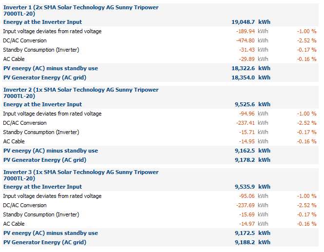
Hi again,
it seems like you found a bug there. It is the combination of offgrid systems with a number of equal inverters and equal module configuration on each inverter. The overall energy balance is correct, as well as the other results. Just the lower level energy balances are not displayed correctly. This bug will be resolved in the next version, sorry for that.
Here are your missing results (in case you need them now):
Cheers,
Martin
-
Hi Salvador,
to decrease the project file size, do the following. Basically you will remove the simulation results form your project file:
- Make a copy of your project file and name it xyz.pvprj. Rename the copy from xyz.pvprj to xyz.zip.
- Open the zip archive and delete the folders "iv" and "iv_noshadow" (if existent), as well as the files core.results and core.results.3600 (if existent).
- In the folder Visu3D delete the files "10min_DirektAbschattungsgrade.bin", "DiffusAbschattungsgrade.bin" and "DirektAbschattungsgrade.bin".
- Close the zip file (save if necessary) and rename it to xyz.pvprj.
- Then you can send it to us.
Kind regards,
Martin
-
Hi Martin,
you can send your models to our technical support (hotline@valentin-software.com) together with your customer number and they will have a look at it.
Kind regards,
Martin
-
Hi Salvador,
could you please send us your project file so that we can have a look at it?
Kind regards,
Martin
-
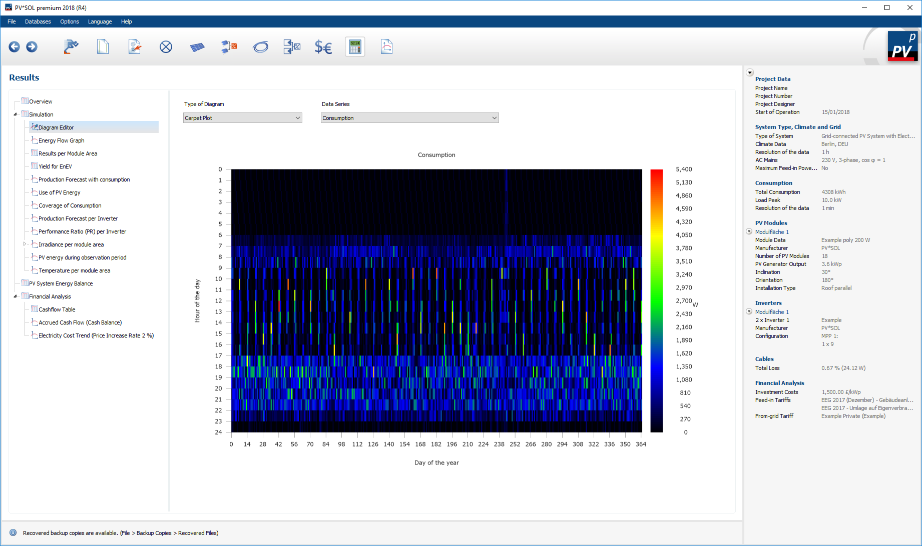
Hi Mads,
yes, you can see that after the simulation. Best way in my opinion is to look at the carpet plots under Results -> Simulation -> Diagram Editor -> Carpet Plots -> Consumption:

Or in Diagram Editor -> Interval, select consumption as data series:
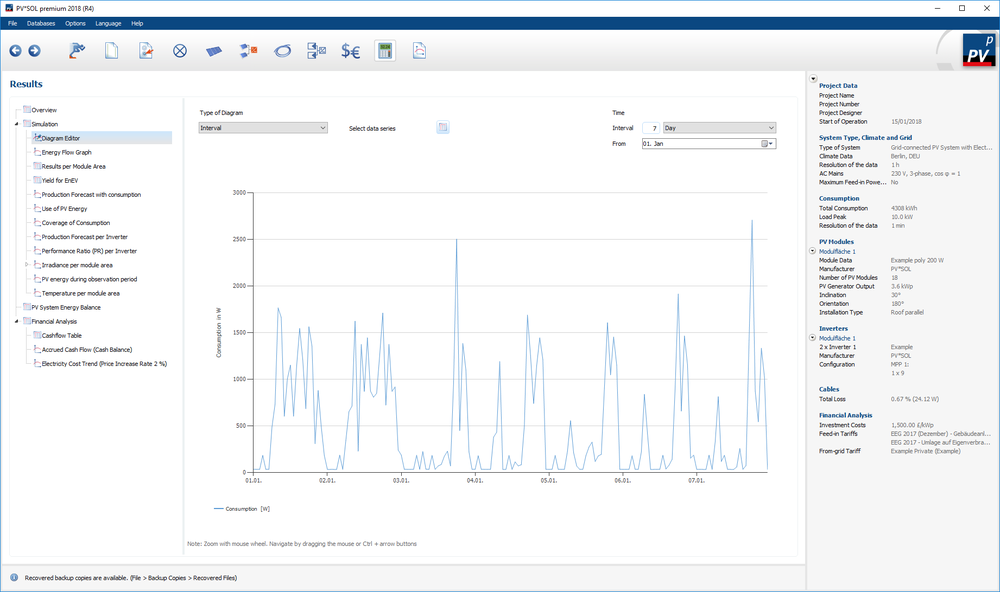
And finally you can export the data as cvs file on the last page.
And please note that the resolution of the exported consumption data will be 1h if you simulate the PV system in 1h time step, even if the consumption profile is in 1min time step. Internally, the simulation of the consumers, own consumption etc will take place in 1min resolution against the values with 1h resolution of the PV, but the logging is set to 1h.
If you want to see the one-minute values of the consumption, you'll have to activate the option under Options -> Programm Options -> Simulation -> "Simulate the irradiance with synthesized minute values"
Kind regards,
Martin
-
cool, thanks a lot for sharing, Martin!
-
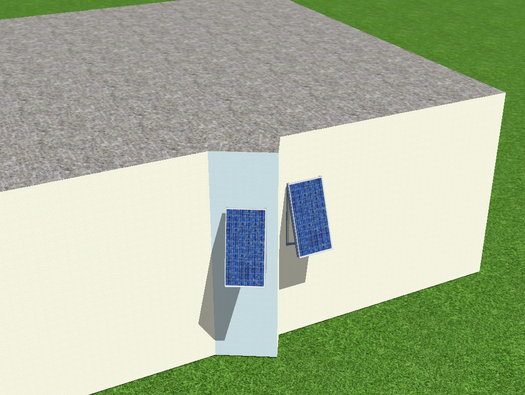
Hi Tobias,
so direkt ist es nicht möglich, die aufgeständerten Fassaden-Module auch um die senkrechte Achse zu drehen. Aber mit einem Hilfskörper, der um die die senkrechte Achse gedreht ist, kann man sich Abhilfe schaffen:

Ich hoffe, das funktioniert so auch für deinen Fall, viel Erfolg!
Beste Grüße,
Martin
-
Hi Martin,
for these kind of problems please contact our technical support (with your customer number) at hotline@valentin-software.com. They should be able to resolve your problem rapidly.
Kind regards,
Martin
-
Hallo Kate0805,
welche Version von PV*SOL premium 2018 nutzt Du denn? Das sieht ein wenig aus wie ein Fehler aus R1 oder R2, der mittlerweile in R4 behoben sein sollte. Wenn du das R4 hast und der Fehler immer noch auftritt, wäre es super, wenn du uns das unverschaltete Projekt schicken könntest mit der Info, an welchen Wechselrichter ihr das verschalten wolltet. Dann können wir das mal nachbauen.
Beste Grüße,
Martin
-
yes, the data must be entered manually. It should only take a few moments
")
-
Hi Khaled,
please have a look in this thread, where the calculation of ROA (return on assets) and IRR (internal rate of return) is explained. I think our calculation of the accrued cash flow that is also explained there fits the common understanding of the net present value:
If have any further questions, please don't hesitate to ask.
Kind regards,
Martin
-
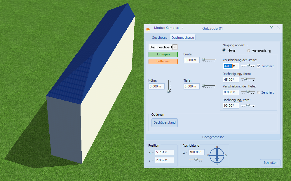
Hallo Alex,
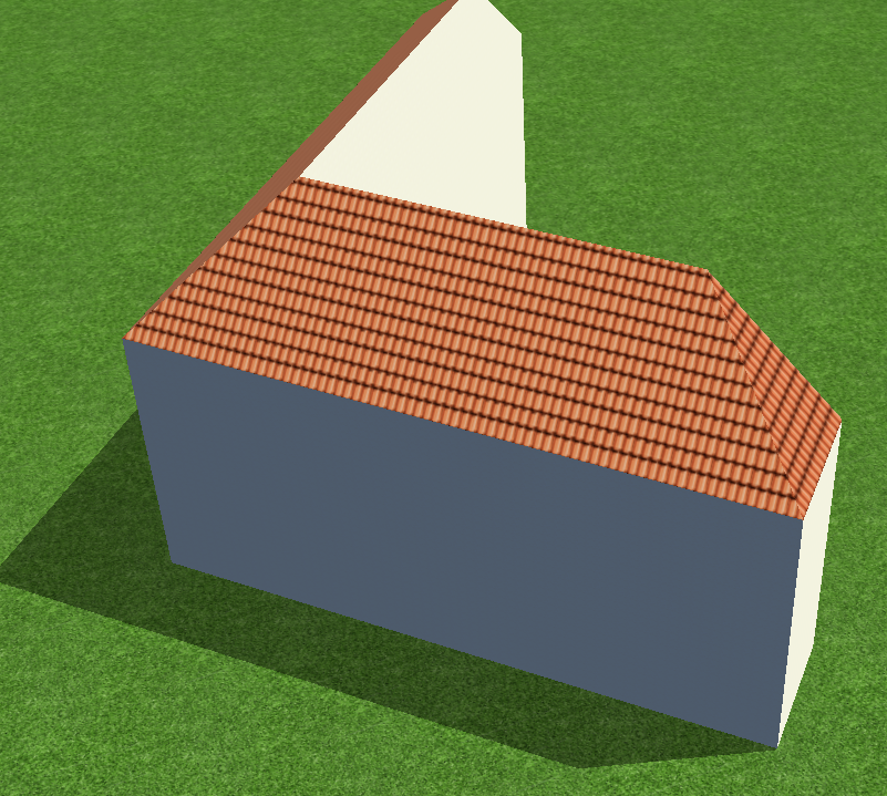
eine Idee wäre, das Gebäude aus vier Teil-Gebäuden zusammenzusetzen. Dazu erstellst du zunächst ein Gebäude mit Walmdach und passt die Dach-Parameter so an, dass eine Seite des Daches vertikal wird:
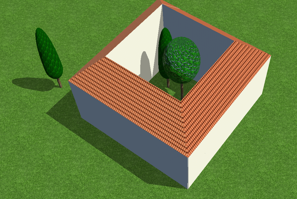
Dann kannst du diesen Seitenflügel duplizieren, die Kollisionen deaktivieren und dann um 90° gedreht in einander schieben:
das wiederholst du für jeden Seitenflügel, schiebst die Ecken genau aufeinander (genauer als ich in diesem Bild) und bekommst dann dein Haus mit Innenhof (sogar bepflanzbar
)
Die andere Option wäre, das Haus in Sketchup oä zu bauen und dann in PV*SOL zu importieren.
Hoffe, das hilft erstmal weiter, beste Grüße,
Martin
-
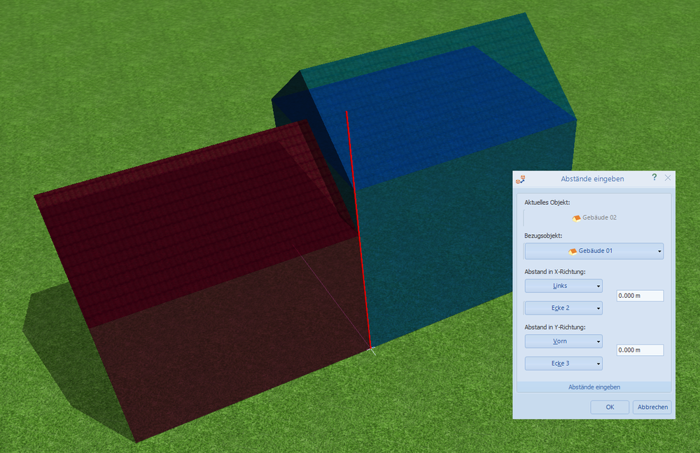
Hallo Alex,
für die genaue Positionierung der Gebäude gibt es die Funktion "Abstände eingeben", erreichbar per Rechtsklick auf einem Gebäude. Dort lassen sich die Bezugsgebäude und -kanten wählen und dann die Abstände zueinander eingeben. Wenn man die Abstände auf 0 m setzt, liegen die Gebäude plan aneinander:
Ich hoffe, das hilft!
Beste Grüße, Martin
-
1
-
-
Hi Esteban,
happy new year!
You don't need to import the shading factors. We calculate the overall diffuse shading factor for each module and the direct shading factors for each module and each simulation time step, so this will be a lot more precise than the averaged values from Skelion. We also detect where exactly the shading occurs on module level, so we can precisely calculate the electrical shading, diode and mismatch losses, also depending on the electrical layout of the PV array and the modules themselves (horizontal or vertical strings). Thanks to our detailed shading analysis you can also investigate the different shadig behaviour of crystalline silicon or thin film modules.
You can export your Sketchup model, without the PV modules perhaps) as *.dae and import it in PV*SOL premium (2018 R1 or newer). Then, in PV*SOL, place your modules where you placed them in Sketchup and connect them to an inverter. Then you can simulate them, and also have a look at the current-voltage characteristics afterwards to see how the shading affects the energy output of your modules.
Hope that helps, kind regards,
Martin
-
Hallo Wolf,
viele Grüße zurück in die Schweiz und ein frohes neues Jahr!
Die Dachsparren lassen sich definieren, indem man das Gebäude (in der Terrainansicht) aktiviert und dann oben in der Buttonleiste auf "Dackonstruktion anlegen" klickt (das Dachstuhl-Symbol).
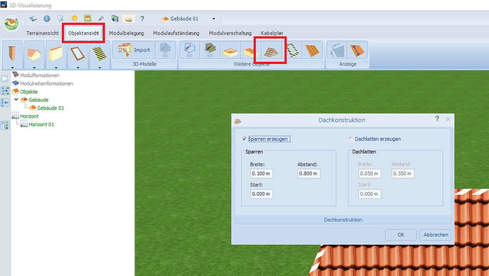
Viel Erfolg weiterhin,
Martin
-
Hi Kamal,
sorry for the late answer. In the screenshot manager in 3D you can right click on any screenshot you have taken and select it as the new overview image of your 3D design.
Hope that helps, kind regards and have a merry holiday time,
Martin


5000 panel limit
in PV*SOL
Posted
Hi James,
yes, we have plans to increase the 5000 limits and we are working on that for the next main version (which is due in autumn). This is a complex task however and involves a lot of refactoring and testing, so we can't come up with the quick solution unfortunately.
We're glad that you like the 3D feature!
Kind regards,
Martin