


developer_mh
-
Posts
1,855 -
Joined
-
Last visited
-
Days Won
173
Posts posted by developer_mh
-
-
Hi Philip Gabriel,
it is not possible to rotate an imported 3D model by 45° in PV*SOL, I am afraid. You would have to rotate it in Agisoft beforehand or check the obj export parameters.
Hope that helps, kind regards,
Martin
-
Hallo deafsquad,
die Hersteller tragen die Werte bei uns eigenhändig ein, da kann der Wirkungsgrad-Wunsch schon mal Mutter der Daten sein, je nachdem wie marketinglastig der jeweilige Mitarbeiter denkt. Wir werden diesen Eintrag bei Sofar melden und sie bitten, ihn gegebenenfalls zu korrigieren.
Vielen Dank und beste Grüße,
Martin
-
Hallo deafsquad,
nein, das ist auf jeden Fall keine Absicht. Da wäre es hilfreich, die Projektdatei zu bekommen, damit ich mal reinschauen kann. Gerne hier im Forum als private Nachricht, danke.
Viele Grüße,
Martin
-
Hi Jan,
Thank you for reaching out and sharing your question with us. Unfortunately, the current configuration process does not support the addition of module arrays without reconfiguring the current configuration.
Kind regards,
Martin
-
Hi michalmitro,
could you contact our technical support team, please? Along with your customer number and your log files, so that they can help you out. Most likely it is an issue with a path or directory that is not found or access privileges are missing or so.
https://valentin-software.com/en/support/technical-support/
Kind regards,
Martin
-
HI PVdesign1654321,
this sounds like a bug that we had some versions ago. Can you specify which version you are using? If it isn't the newest one, please consider updating.
Kind regards,
Martin
-
Hallo Venosta,
das klingt nach einem Bug, der sich vielleicht reproduzieren ließe, wenn wir die Projektdatei hätten. Könntest du sie uns zukommen lassen (also die neuere, korrupte)? Gerne hier im Forum als private Nachricht.
Danke und beste Grüße,
Martin
-
Hallo NeMu,
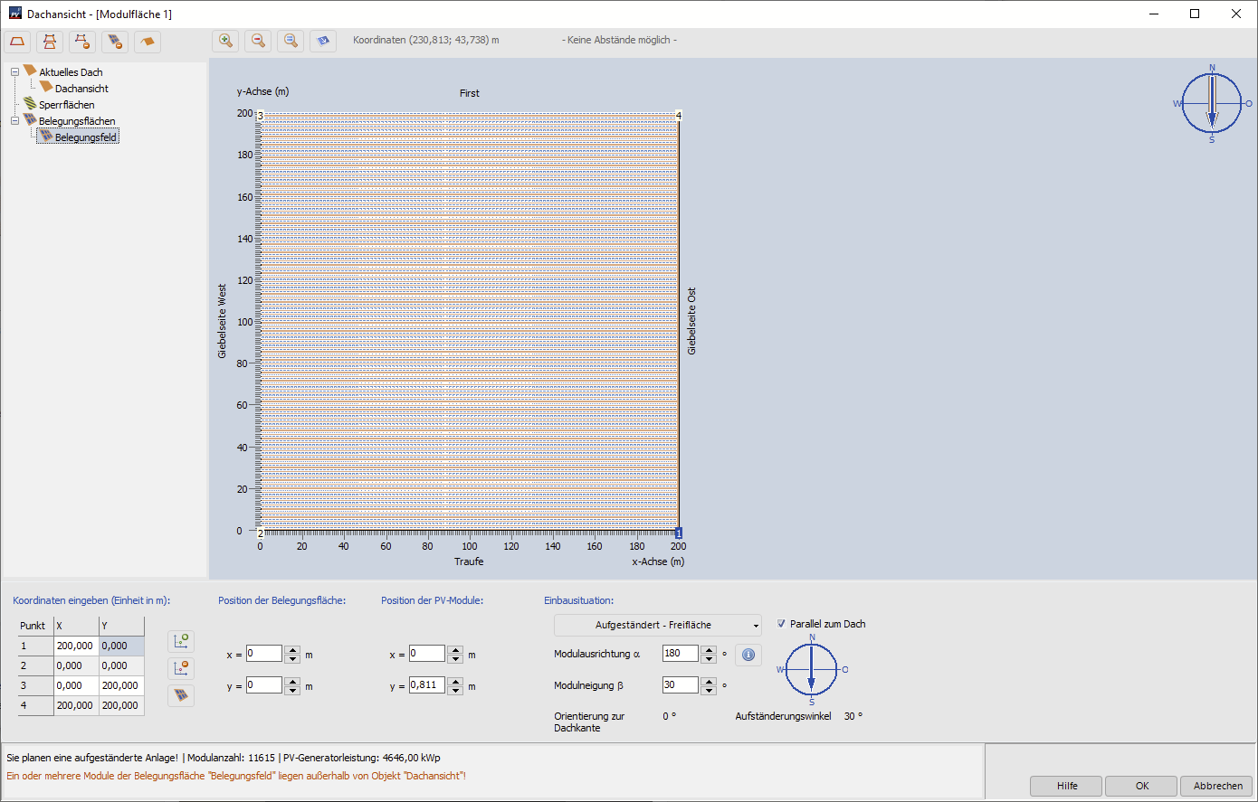
eine 8MWp Anlage am Stück wird wohl auch in der grafischen Belegung nicht klappen. Ich habe mal testweise die größte Belegungsfläche angelegt, die die grafische Belegung zulässt (200m x 200m), und diese mit 1m Reihenabstand mit 400 Wp Modulen belegt. Dabei komme ich auf ca 4,6 MWp. Wenn deine Anlage nicht quadratisch ist, und danach klingt es ja nicht in deiner Frage, dann wirst du pro Modulfläche wesentlich weniger Leistung unterkriegen.
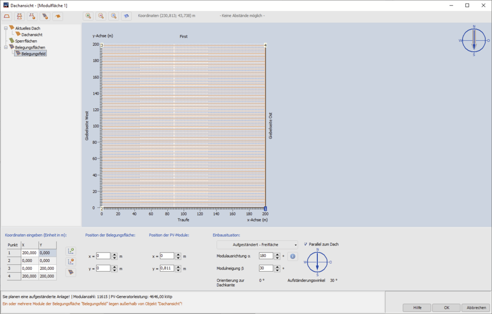
Aber du könntest ja mehrere Modulflächen anlegen und dann einzelne Segmente der Anlage zeichnen, das geht. Das Zeichnen der Polygone kannst du dann innerhalb der "Dachflächen" mit Hilfe der Belegungsfelder machen (man darf sich nur nicht von den Begrifflichkeiten "Aktuelles Dach", "Dachansicht" etc stören lassen).
Beste Grüße,
Martin
-
Danke für das Projekt.
Wie es aussieht, hat sich das Dach der Gaube irgendwie nach unten gedreht. Bei mir half, die Option "ohne Gaubenfirst" zu aktivieren. Danach konnte ich das Dach der Gaube wieder aktivieren.

Beste Grüße,
Martin
-
Hi Venosta,
das ist ja seltsam. Könntest du mir die Projektdatei mal schicken? Gerne hier im Forum als private Nachricht.
Beste Grüße,
Martin
-
Hallo Kristian,
der Anlagennutzungsgrad oder "Performance Ratio" gibt an, wie gut eine Anlage unter den aktuellen Einstrahlungsbedingungen und im Vergleich zum Nennwirkungsgrad unter STC-Bedigungen funktioniert. Dabei spielen alle möglichen Einflussfaktoren eine Rolle, die Verschattung ist nur einer davon.
Die richtige Formel für den Performance Ratio (PR) lautet:
PR = ("PV-Energie (AC) abzgl. Standby-Verbrauch") / ("Globalstrahlung auf Modul" - "Reflexion an der Moduloberfläche") * Modulfläche * Modulwirkungsgrad ))
Um zu verstehen, was alles mit berücksichtigt wird, hilft ein Blick auf die Energiebilanz auf der Ergebnisseite in PV*SOL:
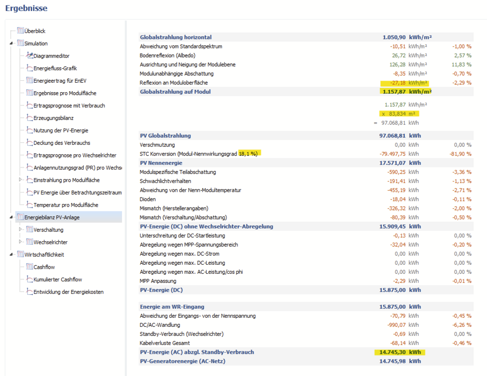
In diesem Beispiel wäre die Rechnung:
PR = 14745,30 kWh / ((1157,87 + 27,18) * 83,834 * 0,181) = 0,82, also 82%.
Alle Posten zwischen der Reflexion oben und der PV-Energie AC unten fließen also in die Berechnung des PR mit ein.
Beste Grüße,
Martin
-
Hi Venosta,
ein Rechtsklick auf die Gaube, dann "Aktivieren" wählen und dann sollte die Gaube mit Modulen belegbar sein.
Viel Erfolg und beste Grüße,
Martin
-
Hi FynnOZ,
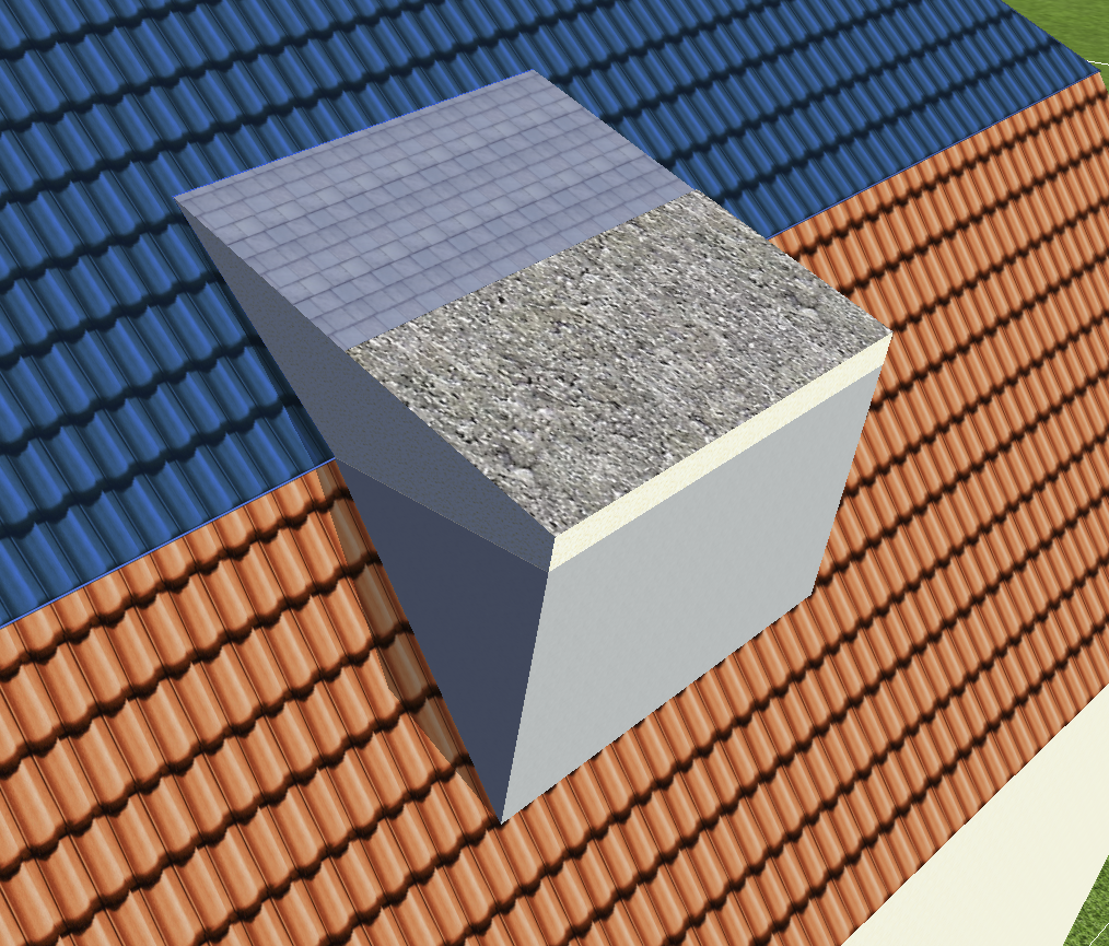
so ohne weiteres geht es leider nicht, aber man kann sich die Gaube aus Einzelteilen zusammenbauen, die jeweils bis zum Stoß der Dachflächen gehen. Ich hab das mal grob zusammengebaut, mit unterschiedlichen Texturen, so dass man die drei Einzelteile der Gaube erkennen kann.

Den oberen Teil habe ich mit einer normalen Schleppgaube realisiert. Auf der unteren Dachfläche habe ich zuerst ein "Beliebiges 3D-Objekt" extrudiert, und darauf dann nochmal ein "Beliebiges Gebäude" (das mit der Beton-Textur).
Hoffe, das hilft weiter, beste Grüße,
Martin
-
Hi David,
yes, you'll need to create a copy of this battery system first. Then you can change the coupling type.
Kind regards,
Martin
-
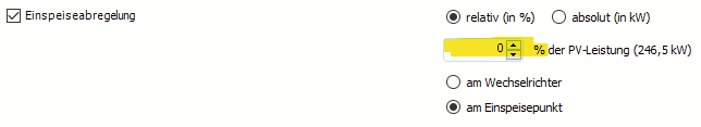
Hallo Bernd75,
danke für die Projektdatei. Die Einspeiseabregelung ist hier genau anders herum zu verstehen. 0% bedeutet, es geht nichts in Netz.
Beste Grüße,
Martin
-
I just found a nice diagram that illustrates one possible connection:
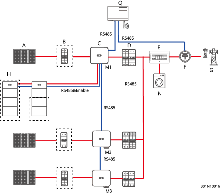
from https://support.huawei.com/enterprise/de/doc/EDOC1100173562/c29b9ead
So yes, this is only possible if you change the coupling type to AC.
-
Hi David Pereira,
the charging of DC coupled battery systems by more than one inverter is not possible in PV*SOL right now. You could change the coupling type to AC, so that energetically you get closer to the real thing.
Can you point me to a description of the connection possibilities of the M2 or M3 inverters to the Luna 2000?
Thanks a lot and kind regards,
Martin
-
Hi Kashyap,
I had a look at the datasheets of the three products that Tricera Energy is offering currently:
-
Utility-scale battery energy storage solutions
> 2 MWhUtility-scale battery energy storage solutions
Flex100e: The Industrial battery energy storage systems indoor
-
Flex400e: The Industrial battery energy storage systems outdoor
-
The Utility-scale battery energy storage solution
The Flex100e has a usable battery energy of around 90 kWh, the Flex400e has 353 kWh and the large one can have up to 3.6 MWh. So from those numbers I would guess that the Flex400e has four times more battery cells than the Flex100e (4 * 90 kWh = 360 kWh). And the large system can have up to 40 times more battery cells (40 * 90 kWh = 3600 kWh).
The Tricera Flex100e in our database has 16 batteries per string and a usable battery energy of 83.4 kWh (a bit less than in the datasheet, since we only count the energy from the minimum to the maximum SOC).
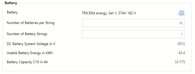
So the Flex400e (not in our database) should have 16*4=64 of those batteries, wheres as the largest system should have 16*40=640 batteries.
Hope that clarifies the matter a bit. Best regards,
Martin
-
 1
1
-
-
Hi Codrin Somesan,
you can see how to change the limit (along with note of caution
") ) here:
) here:
Kind regards,
Martin
-
Hi Martinovec,
in the 3D environment you can right click objects and select "Edit". Then you can enter the dimensions.
Hope that helps. If you were referring to something else, please elaborate (perhaps with a screenshot).
Thanks and kind regards,
Martin
-
Hi Sk9,
can you tell us which interverter models you tried?
Kind regards,
Martin
-
Hi George,
thanks a lot for the project files. The calculation of the shading losses is a complex algorithm that can lead to small differences in the results depending on how the PV modules are connected. Especially the calculation of the shading losses in module independent and module specific losses can vary a little. Please also see this thread:
Also, regarding the mismatch losses in the SolarEdge project, there is a 1 x 2 power optimizer layout in your configuration which is more susceptible to mismatch losses than the 1 x 1 layout.
Hope that helps, best regards,
Martin
-
Hi Gejege,
interesting question, thanks for that. It is one advantage of a simulation software like PV*SOL that you can compare the different options directly. And yes, it might be astonishing at first sight that a PV system equipped with SolarEdge power optimizers isn't always the best option in terms of PV yield, but it is true. It always depends on the exact configuration and the shading situation.
In order to go into detail a bit more it would be helpful to get the project files. You can send them to me as private message here in the forum.
Thanks a lot, kind regards,
Martin
-
Hallo Bernd75,
die Einspeiseabregelung ist eigentlich genau der richtige Ansatz. Verwunderlich ist, dass die Einstellung nicht in der Simulation und in den Wirtschaftlichkeitsergebnissen nicht berücksichtigt wird.
Vermutlich wäre es das einfachste, wenn du dein Projekt hier zur Verfügung stellen könntest. Gerne an mich als private Nachricht hier im Forum.
Danke und Grüße,
Martin

Energy yield estimates
in PV*SOL
Posted
Hi Luís,
yes, sure, you can have P90 or P70 or anything you want. Have a look here:
https://help.valentin-software.com/pvsol/en/pages/financial-analysis/bankability/
Note that this feature only works for PV system types without electrical appliances.
Kind regards,
Martin