
Joao Prates
-
Posts
31 -
Joined
-
Last visited
-
Days Won
3
1 Follower

Joao Prates's Achievements
")


-
Hi all, I'm designing a system with 2 inverters and one large battery, one of the inverters being a Fronius SYMO GEN24 10.0 Plus. The battery is connected to the GEN24 inverter, and the 2nd inverter is only acting as an extra AC power generator (AC coupling) to the main AC bus. One of the innovative features of the Fronius GEN24 is its ability to act both as a DC coupling (energy source is PV) and AC coupling (AC bus is source) simultaneously. This is key to our design, as the second inverter will provide for extra power to be injected into the battery, adding to GEN24's own PV DC coupling. For example if GEN24 PV is producing 4 kW and the other inverter is injecting 2 kW into the AC bus, the battery will get the 6 kW sum, minus the AC consumption of course. We're using PV*SOL 2020 (R5) and the Fronius GEN24 is supported, in fact it is even supported in conjunction with the battery we are using, so we thought the simulation was fine. Unfortunately upon running the simulation we got grid feed energy way too high for what we anticipated. Upon checking the csv simulation results we were shocked to realize there is energy exported to the grid even with a low battery SoC and coupling capacity available! PV*Sol is not doing battery AC coupling on the GEN24, all energy produced by the second inverter over the AC bus is being ignored the GEN24, so the production surplus over consumption is being fed to the grid instead of getting into the battery. Can you please provide proper behavior for this inverter in your simulations by adding simultaneous DC and AC coupling? Thanks in advance, -jprates
-
Sure, anything I can do to help you improve the software you can count on it. I'm not here just to point out errors, I will do my best to help you solve them. Just note that the project will show correct naming already, as I've spent many hours fighting with it till I got all nodes correctly named and saved. Check your inbox in 5 minutes time.
-
Martin, I was genuinely thinking it was my fault the data was not being adopted, that I had done something wrong. It never crossed my mind this could be the intended behaviour by design. The logical approach (at least to me) would be to use 3D to take precise length measures and then adopt them into the 2D design. I always assumed this was the case. As it is it makes absolutely no sense at all, I can't understand why was this module designed like this, and I see it's not just me. What you're saying is that all of the trouble of designing combiner boxes, different cable sections, strings combined into arrays, etc, it all disappears into ONE SINGLE magic number. Just as @timgreen13 pointed out, one is expecting to see cable losses by section, see individual string lengths and losses, etc, because if not then what's the point of all that detailed "painting"? We need to check if individual strings and individual arrays are above our own loss thresholds, to be able to correct them if necessary. Having just one global loss number won't let you see that, you might even have 5% losses in one string branch and get 0,8% global losses in the system. Again I'm in the position of having this powerful software (PVSOL) I paid for that won't do basic functionality, and having to go back to freeware manufacturer software (SUNNY DESIGN) to get some of the design steps done. After fine tuning the strings and cable sections on SUNNY DESIGN I will have to go back to PVSOL and try to input MPPT equivalents... can you see how cumbersome this is? The more I work with PVSOL the more frustrated I get, really, it should be the opposite. You guys do the most difficult part, the math simulations, to unimaginable precision (congrats on that!), and then fail at the most basic functionality and design elements. Go figure...
- 3 replies
-
- 3
-

-
- cable plan
- adopt data
- (and 1 more)
-
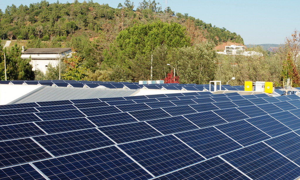
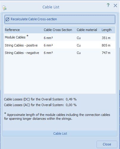
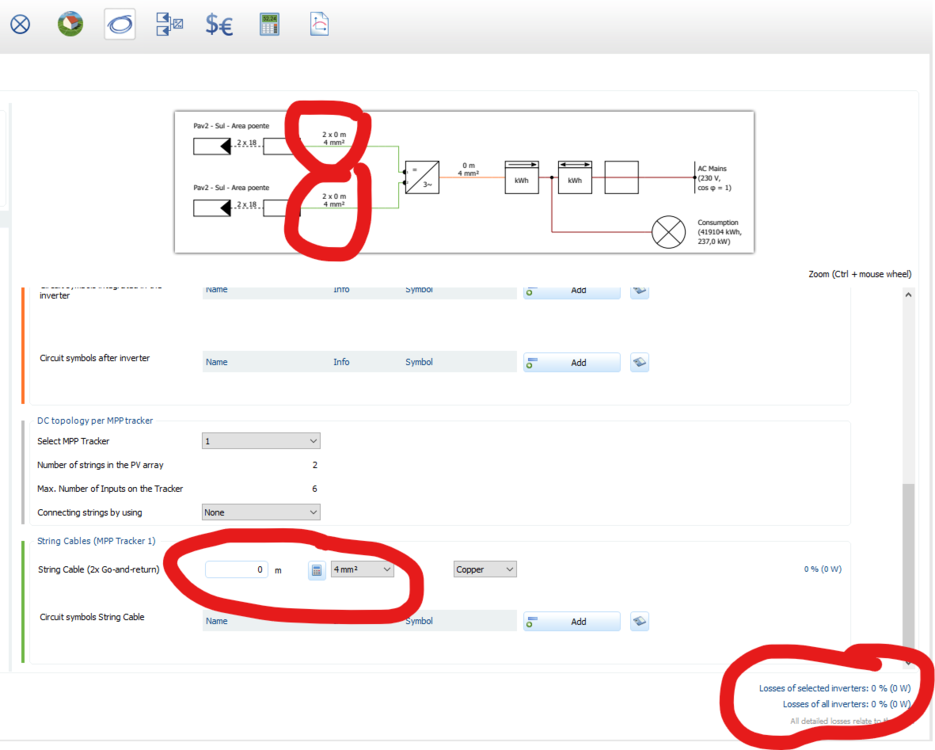
Hi, I wonder if someone could explain this, meaning pointing out where did I go wrong, because this can't be default/desired behaviour and most probably I'm the one at fault: A complete system design was done in 3D, including cabling, which gave me these lengths and losses (as seen inside 3D module): As a side note, I don't understand what is AC losses value doing there, since I could find no way to detail AC cabling inside the 3D Design.. can anyone care to let me know where is it? The main issue of this post is to ask the community where did I go wrong, because I did system check, all was OK, chose "Adopt data" from main menu, only to find this at PVSOL cable section: Unless I'm missing some step or setting, it seems PVSOL is totally ignoring all the cable lengths and sections detailed in 3D Design, leading to default values and zero losses. What did I do wrong? TIA -jprates
-
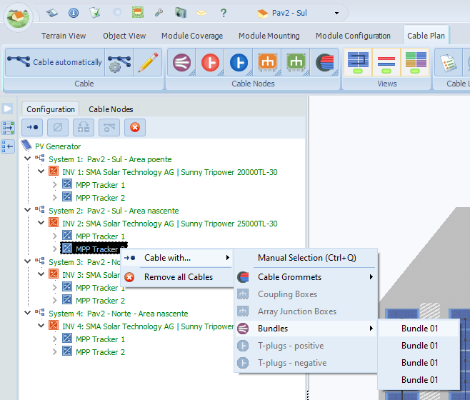
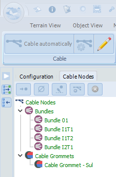
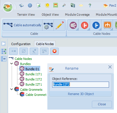
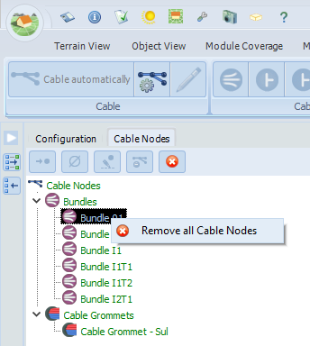
Hi, Yes, I know, you're working on a new 3D module that won't be ready for 18 months... Yes, I know, you're not planning to introduce new features or even correct bugs on current 3D... However... I really think a line should be drawn somewhere, because as it stands some 3D features are just about useless and desperating if we try to use them. I'm trying to use 3D "Cable Plan" feature and it's really driving me nuts, the object/node tree refresh is almost never happening, no matter how many times we rename a node. One gets things like this: Obviously there are not 4 bundles with the same name, they all have been renamed, but the configuration tree refuses to load the new names. This happens with all kinds of nodes, it's desperating really! How are we suppose to guess to which node do we want to connect or do any operation for that matter? On the same exact scenario and without doing anything but switching to the "Cable Nodes" tab on the object tree, we get this: Sometimes no nodes have updated names, sometimes only some have, in this case all but the first were showing the correct renamed titles. If we select the node not displaying the correct name and ask to rename it again, it shows the correct title, it's crazy: I'm sorry, but this puts cable design completely on the zero usability department, it's a nightmare to work in design in this circumstances. Please do something about this refresh problem ASAP, it's not usable at all as it stands. -jprates EDIT: Forgot to add this other annoying issue in the same cable module: This is happening ALL THE TIME, we select one node, right click to do some operation on it, and the only option that appears is to remove all cable nodes. Argh. EDIT 2: Just came back from lunch, opened the saved project file, and found out that all the renamed nodes that were not showing in the tree were saved with the original/wrong names. So all of the work done renaming the nodes is lost, and we have to rename them again, only to find out some will refuse to be renamed, and so on... this bug is a nightmare.
-
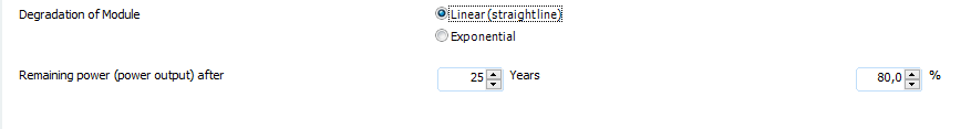
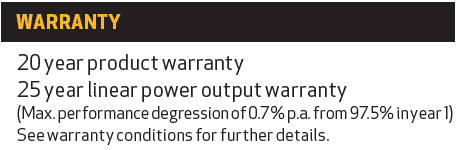
Hi, Submiting a New Feature Request for the PV*SOL dev team: Currently module degradation inputs are only 2 fields, one for the age and the other for the remaining power: Most modules we work today though offer a warranty with linear degradation AFTER FIRST YEAR, meaning the value for the 1st year is always different (and higher) than average. For example we have this module as many others on the market: In order to support this, we need another field to enter the first year degradation (0,3% in the above example), and the other fields could still be as they are. Of course having the option to specify the degradation per year after the 1st year instead of having to manually compute the remaining power would also be a nice to have, but not critical. TIA
-
Judging by your test case it would seem to be a problem related to some change in the way the project is being saved on 2020R2 vs 2019R14. This project was originally created on 2019R14, hence my suggestion. Next week will be fine, don't worry, this is not a blocking issue at this stage. Thanks for the quick feedback. EDIT: Tried your suggestion of removing and adding back the horizon and it worked. You can change the priority of this bug to "minor" as far as I'm concerned.
-
It's friday and we can wait for monday, no problem. I'll try to send it via pm as requested.
-
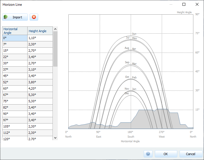
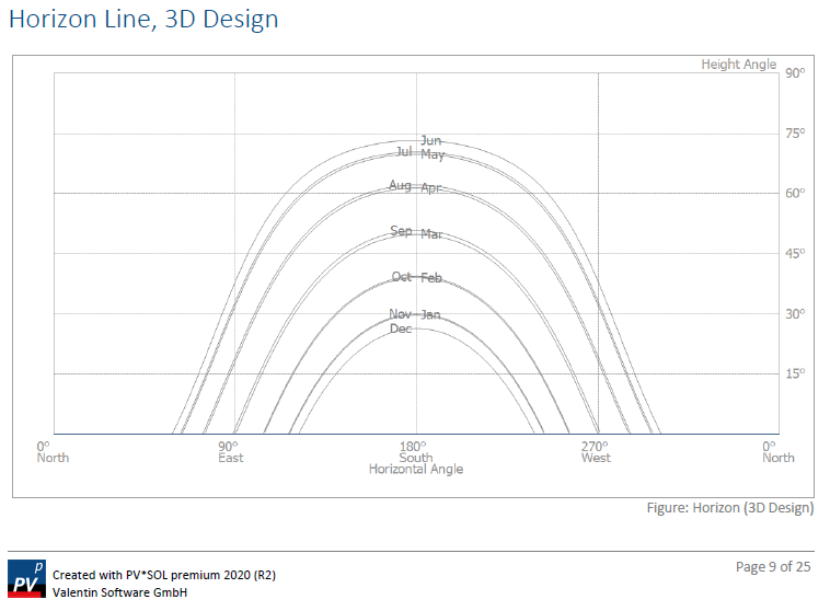
Hi, I think I may have found a bug on the presentation report. Using the 3D design module I have loaded this realistic horizon into the project: When generating the report back on the main program window, this is what gets generated: Now apart from the obvious error of not using the 3D horizon, I am left with the more important doubt about the yield results, since obviously the correct horizon has impact on the determined values and I wonder which of horizons was used, if the 3D real horizon or the flat one from the report. Can you please investigate and provide feedback on this? Thank you.
-
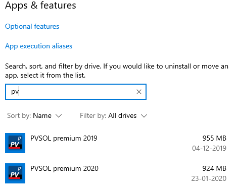
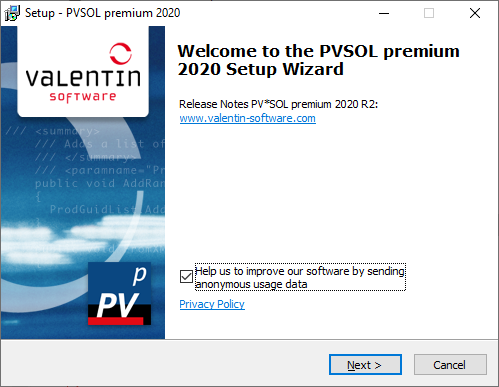
Errr... guys just one question... is this normal? I was assuming that by accepting the 2020 setup I was asking for an upgrade, not an extra install... Just realized after calling PVSOL that the old 2019 version was still being called and executed, it was not uninstalled at all. Shouldn't the 2020 setup uninstall the 2019 prior to installing itself? What now? Is it safe to uninstall the 2019 version, or will this currupt and/or delete registry keys used by 2020 and I should reinstall 2020 once again after uninstalling 2019? Argh... what a mess... not the best way to start using PVSOL 2020!
-
HURRAY!!!! ?
-
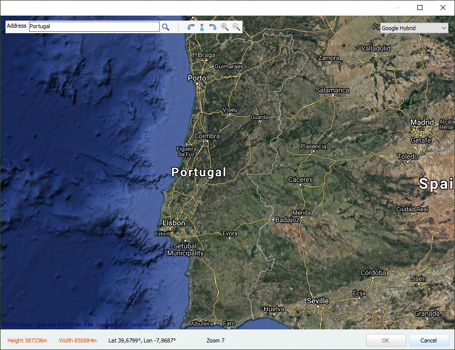
Glad to know about the fix, thanks. About the map API, without being much of a priority comparing to other issues, it would be nice to have it reviewed or to use other tool. Right now for a couple of projects of mine I had to take a google maps print screen at a more appropriate scale and then manually enter the scale on PVSOL. This quite defeats the purpose of this feature having the maps right there.
-
Yes, please do put QA over any release rush! Can't wait to take it out for a spin though...
-
Hi, PV*SOL premium 2019 (R14) When creating a new 3D system from a map, the rotating tool arrows on the small tool box ribbon do not work, neither of them, Rotate Left or Rotate Right. The zoom level on the other hand is quite aggressive, it would be nice to have at least the double number of steps while zooming in and out. Video demonstration: Don't know if this goes on time for the new release next week, but it would be nice to see it, even if on a patch level build afterwards. Cheers, -jprates
-

import 3D model fallacy - beware of its very limited usefulness
Joao Prates replied to Joao Prates's topic in PV*SOL
Thanks for the feedback, I truly appreciate it. Agree that as a design and general analysis tool PVSOL is probably one of the best out there, if not the best, no contest there. I think we need to distinguish 2 situations here: One is about requests for new features which to me seem basic and should have been there since ever (example full cabling systems) and another quite different is bug fixing to let existing features work as designed/advertised by Valentin Software. I’m resigned with waiting 1.5 years for a proper 3D module, and basic missing features missing like allowing AC junction boxes, cabling of mounting systems, etc. But neither I nor anyone can accept VS refusing to fix horrific bugs in memory allocation that prevent advertised existing functionality to work. If you have an application that crashes with out-of-memory error when it's only using 1.5GB out of 16GB with over 10 GB available, you need to accept there is a bug and fix it. EDIT: Let's not get off-topic. The purpose of this thread is to warn others not to fall into the 3D photogrammetry import trap on PVSOL, it's not about my problems.
