Support Team, thanks for your quick response.
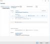
The real cause of my inverter not appear is that their configuration was different phases of the system, corrected.
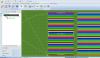
The real problem I have is that my inverter is 12 entries DC, I planned 7 parallel series of 16 modules in series per entry, so I grouped the modules in the 2 areas of modules, but the program creates 84 series of 16 modules in series and I find no way to configure the parallel connections. Judging by the color code, it will apparently accommodating each series of 16 at an input, so that the row i + 12n is assigned to the input i.
That I like is that rows 1-7 will be connected to input 1. 8 to 14 to the second, and so on. Is this possible? Can you help me?
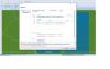
By the way, how can I pan, zoom or rotate the image in the graphic view?