A) Improved the function of exporting plan diagram strings to CAD files (dxf, dwg) to allow the ENTIRE plan to be exported in a single file at the same time, and not separated by assembly area.
- The size of the string identification letters is too small in the exported model. It should be possible to adjust the size of the letters according to the size of the plot sheet, or redirect all identification to a side legend;
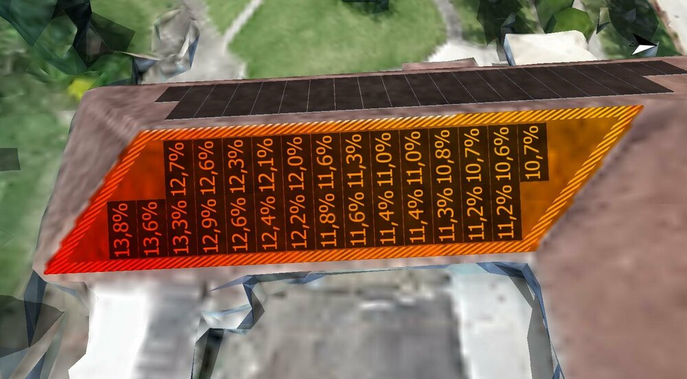
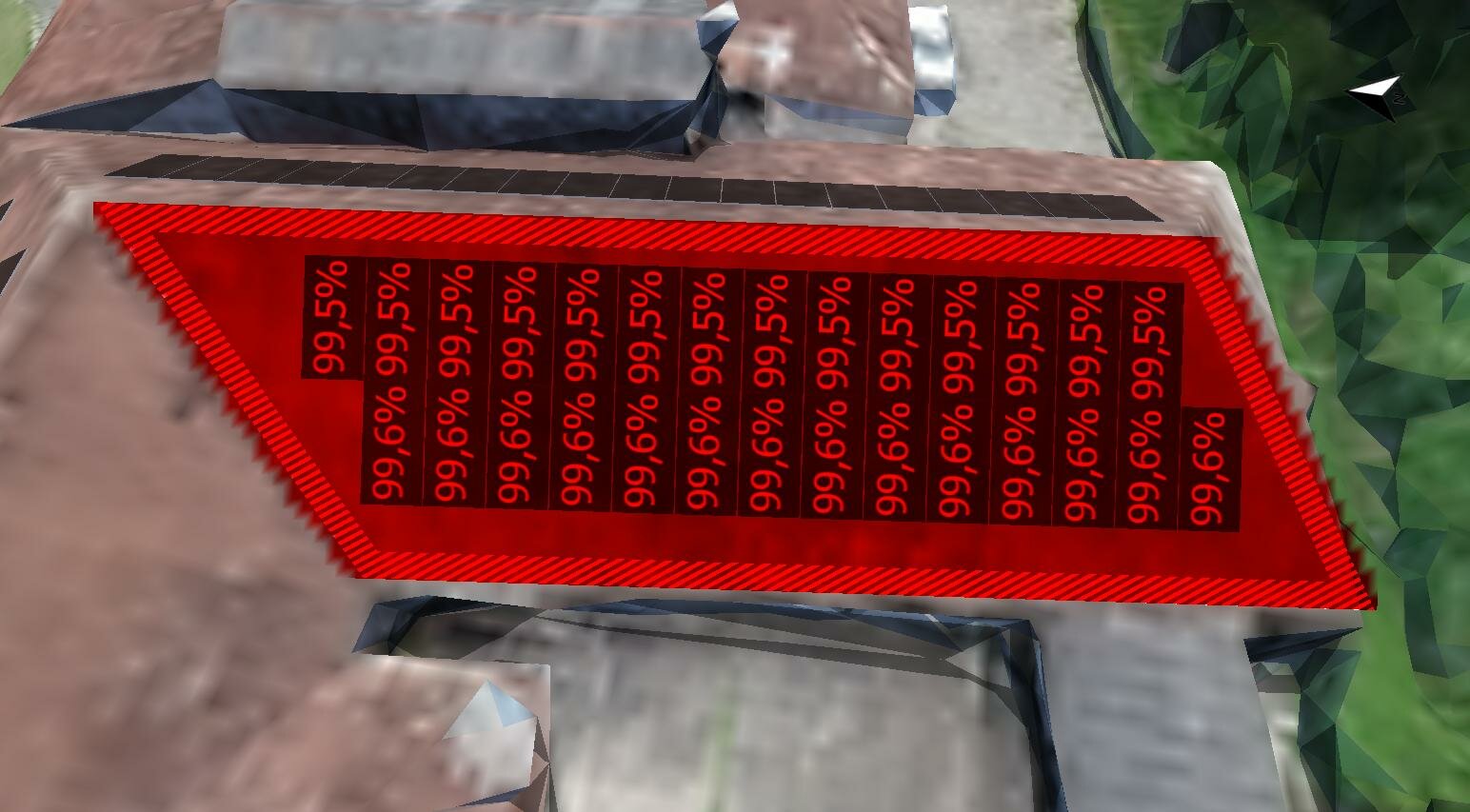
The drawing of cables is often unnecessary and moreover it pollutes the file when you just want to have the string plan. Ideally, it would be possible to choose to have the dxf/dwg similar to the layout obtained in the 3D view in the inverter configuration part (image below), with, of course, being possible to see the numbering letters of the modules, which is not possible when viewing the entire system.
The limitations of exporting separately by assembly area makes this function often useless, as you have to copy and paste each of the areas into a CAD software to allow editing the floor plan drawing.
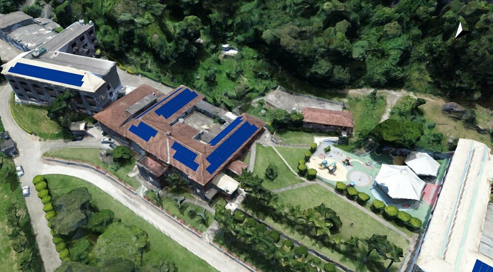
In addition, exporting the file should also allow loading of building data, such as the top view image of the model itself, or, even better, the edges of the building and the roofs in floor plan, since exporting only the string design brings a poor project data since it does not carry any information from the other 3D objects involved in the scenario.
A complete export functionality of the design in detail to editable CAD file is essential for anyone working with large projects where documentation and design detailing is required. In the current model, with poor information from the model exported from PVSol, a large rework is practically always necessary (and with very low design time efficiency) as it is necessary to redesign the entire plant in CAD software.


")